
Loose Leaf for Engineering Circuit Analysis Format: Loose-leaf
9th Edition
ISBN: 9781259989452
Author: Hayt
Publisher: Mcgraw Hill Publishers
expand_more
expand_more
format_list_bulleted
Concept explainers
Videos
Textbook Question
Chapter 5, Problem 18E
- (a) Using repeated source transformations, reduce the circuit of Fig. 5.62 to a voltage source in series with a resistor, both of which are in series with the 6 MΩ resistor.
- (b) Calculate the power dissipated by the 6 MΩ resistor using your simplified circuit.
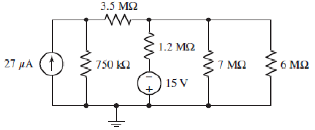
■ FIGURE 5.62
Expert Solution & Answer

Trending nowThis is a popular solution!

Students have asked these similar questions
Find the current across the resistor 5 52 while the switch
S is open for a long time.
A) (A)
B)(A)
C) (A)
3 V
192
ΖΩΣ
D) (A)
26
3ΩΣ
5 V
E) (A)
4 V
www
:552
how long will it take to charge a 1000μF capacitor through 1 KQ resistor to
full 16V source voltage? d) forever
a) 1000 microseconds
b) 10seconds
c) one day
d)
forever
What maximum voltage can be safely applied to series resistors, 1.2 KQ ¹4 W
and 680 0%W?
a) 9.81V
b) 17.32. V
c)27.07 V
d) 32.52V
When a capacitor is being charged from a 12V power source, the current
flowing through thecapacitor will
a} increase
b} decrease
c) remain the same
d) can't be determined
Calculate the voltmeter reading in the circuit shown in the figure when wiper
arm of the potentiometer is set at 25% up fromthe bottom. note: the
resistance value is 3.3 Kilo-ohms.
9V
Oa) 2.13 V
b) 3.12 V
c)2.31 V
d) 6.25 V
1k
3k3
how long will it take to charge a 1000μF capacitor through 1 KQ resistor to
full 16V source voltage? d) forever
a) 1000 microseconds
b) 10seconds
c) one day
d) forever
What maximum voltage can be safely applied to series resistors, 1.2 KQ 14 W
and 680 0%W?
a) 9.81V
b) 17.32. V
c)27.07 V
d) 32.52V
When a capacitor is being charged from a 12V power source, the current
flowing through thecapacitor will
a} increase
b} decrease
c) remain the same
d) can't be determined
Calculate the voltmeter reading in the circuit shown in the figure when wiper
arm of the potentiometer is set at 25% up fromthe bottom. note: the
resistance value is 3.3 Kilo-ohms.
9V
a) 2.13 V
b) 3.12 V
c)2.31 V
d) 6.25 V
1k
3k3
Chapter 5 Solutions
Loose Leaf for Engineering Circuit Analysis Format: Loose-leaf
Ch. 5.1 - For the circuit of Fig. 5.4, use superposition to...Ch. 5.2 - For the circuit of Fig. 5.7, use superposition to...Ch. 5.2 - For the circuit of Fig. 5.18, compute the current...Ch. 5.2 - For the circuit of Fig. 5.20, compute the voltage...Ch. 5.3 - Using repeated source transformations, determine...Ch. 5.3 - Use Thvenins theorem to find the current through...Ch. 5.3 - Determine the Thvenin and Norton equivalents of...Ch. 5.3 - Find the Thvenin equivalent for the network of...Ch. 5.3 - Find the Thvenin equivalent for the network of...Ch. 5.4 - Consider the circuit of Fig. 5.43. FIGURE 5.43...
Ch. 5.5 - Prob. 11PCh. 5 - Linear systems are so easy to work with that...Ch. 5 - Prob. 2ECh. 5 - Prob. 3ECh. 5 - (a) Employ superposition to determine the current...Ch. 5 - (a) Using superposition to consider each source...Ch. 5 - (a) Determine the individual contributions of each...Ch. 5 - (a) Determine the individual contributions of each...Ch. 5 - After studying the circuit of Fig. 5.53, change...Ch. 5 - Consider the three circuits shown in Fig. 5.54....Ch. 5 - (a) Using superposition, determine the voltage...Ch. 5 - Employ superposition principles to obtain a value...Ch. 5 - (a) Employ superposition to determine the...Ch. 5 - Perform an appropriate source transformation on...Ch. 5 - (a) For the circuit of Fig. 5.59, plot iL versus...Ch. 5 - Determine the current labeled I in the circuit of...Ch. 5 - Verify that the power absorbed by the 7 resistor...Ch. 5 - (a) Determine the current labeled i in the circuit...Ch. 5 - (a) Using repeated source transformations, reduce...Ch. 5 - Prob. 19ECh. 5 - (a) Making use of repeated source transformations,...Ch. 5 - Prob. 21ECh. 5 - (a) With the assistance of source transformations,...Ch. 5 - For the circuit in Fig. 5.67 transform all...Ch. 5 - Prob. 24ECh. 5 - (a) Referring to Fig. 5.69, determine the Thevenin...Ch. 5 - (a) With respect to the circuit depicted in Fig....Ch. 5 - (a) Obtain the Norton equivalent of the network...Ch. 5 - (a) Determine the Thevenin equivalent of the...Ch. 5 - Referring to the circuit of Fig. 5.71: (a)...Ch. 5 - Prob. 30ECh. 5 - (a) Employ Thvenins theorem to obtain a...Ch. 5 - Prob. 32ECh. 5 - Determine the Norton equivalent of the circuit...Ch. 5 - For the circuit of Fig. 5.75: (a) Employ Nortons...Ch. 5 - (a) Obtain a value for the Thvenin equivalent...Ch. 5 - Prob. 36ECh. 5 - Obtain a value for the Thvenin equivalent...Ch. 5 - With regard to the network depicted in Fig. 5.79,...Ch. 5 - Determine the Thvenin and Norton equivalents of...Ch. 5 - Determine the Norton equivalent of the circuit...Ch. 5 - Prob. 41ECh. 5 - Determine the Thvenin and Norton equivalents of...Ch. 5 - Prob. 43ECh. 5 - Prob. 44ECh. 5 - Prob. 45ECh. 5 - (a) For the simple circuit of Fig. 5.87, find the...Ch. 5 - For the circuit drawn in Fig. 5.88, (a) determine...Ch. 5 - Study the circuit of Fig. 5.89. (a) Determine the...Ch. 5 - Prob. 49ECh. 5 - Prob. 50ECh. 5 - With reference to the circuit of Fig. 5.91, (a)...Ch. 5 - Prob. 52ECh. 5 - Select a value for RL in Fig. 5.93 such that it...Ch. 5 - Determine what value of resistance would absorb...Ch. 5 - Derive the equations required to convert from a...Ch. 5 - Convert the - (or "-") connected networks in Fig....Ch. 5 - Convert the Y-(or T-) connected networks in Fig....Ch. 5 - For the network of Fig. 5.97, select a value of R...Ch. 5 - For the network of Fig. 5.98, select a value of R...Ch. 5 - Prob. 60ECh. 5 - Calculate Rin as indicated in Fig.5.100. FIGURE...Ch. 5 - Employ Y conversion techniques as appropriate to...Ch. 5 - Prob. 63ECh. 5 - (a) Use appropriate techniques to obtain both the...Ch. 5 - (a) For the network in Fig. 5.104, replace the...Ch. 5 - Prob. 66ECh. 5 - Prob. 67ECh. 5 - A 2.57 load is connected between terminals a and...Ch. 5 - A load resistor is connected across the open...Ch. 5 - A backup is required for the circuit depicted in...Ch. 5 - (a) Explain in general terms how source...Ch. 5 - The load resistor in Fig. 5.108 can safely...Ch. 5 - Prob. 74ECh. 5 - As part of a security system, a very thin 100 ...Ch. 5 - With respect to the circuit in Fig. 5.90, (a)...
Knowledge Booster


Learn more about
Need a deep-dive on the concept behind this application? Look no further. Learn more about this topic, electrical-engineering and related others by exploring similar questions and additional content below.Similar questions
- Consider the circuit shown below. [5] Determine and sketch the Norton equivalent circuit and indicate all element values clearly. 5Ωarrow_forwardQuestion 18 a) Using repeated source transformations, reduce the circuit of Fig. 5.62 to a voltage source in series with a resistor, both of which are in series with the 6 MS2 resistor. b) Calculate the power dissipated by the 6 MS2 resistor using your simplified circuit. 27 ΜΑ (1) FIGURE 5.62 3.5 ΜΩ www 750 ΚΩ 1.2 ΜΩ 15 V 7 ΜΩ 6 ΜΩarrow_forwardQ17. For the circuit shown in Figure 5.23 calculate (a) the value of resistor Rx such that the total power dissipated in the circuit is 2.5kW, and (b) the current flowing in each of the four resistors. 4 Rq=15 2 a A3=38 2 R2=10 2 Rx 12 14 V2² 250 Varrow_forward
- LMH_chapter3-part 1-homework [Protected View] PowerPoint ĐĂNG PHẠM HỒNG File Home Insert Design Transitions Animations Slide Show Review View Help Tell me what you want to do & Share 6. HW18 5.20 In the circuit of Fig. 5.59, calculate v, of v; = 0. HW20 8 ka 4 4 ka 5.32 Calculate iz and v, in the circuit of Fig. 5.70. Find the power dissipated by the 30-kN resistor. 7 HW19 3.24 In the circuit shown in Fig 5.62, find k in the voltage transfer flunction ,- , 48 k2 ww ww 8 4 mV 50 k2 HW20 60 k2 30 Ω 5.32 Calculate i, and e, in the circuit of Fig. 5.70. Find the power dissipated by the 30 kl resistor 10 kΩ 4 mv ( 50 ka 60 30 k2 10 k2 9. HW21 5.33 Re:kn lo the p m tineuit in Fip 571 Caknulale4 ud the pomer disupated by dhe kil resistor. 1 kI 8 3 ma O ww- wwarrow_forwardCan someone please help me out and provide the full solution and answer for this example, I need it as my reviewer. Thank you so much!arrow_forwardIf no node was encountered more than once, then the set of nodes and elements that we have passed through is defined as a closed path. Select one: O True Falsearrow_forward
- A point at which two or more elements have a common connection is called a mesh. Select one: O True Falsearrow_forwardQuestion 48 Study the circuit of Fig. 5.89. a) Determine the Norton equivalent connected to resistor Rout. b) Select a value for Rout such that maximum power will be delivered to it. 4 A FIGURE 5.89 ΚΩ 3 V 2 V 2 kΩ Routarrow_forward5. A conductive block in the shape of a rectangular solid has a cross-sectional area of 12 cm2 across its width, and a length of 16 cm. The block has a resistance of 220 Ω. The block contains 7e+18 conduction electrons (be careful, this is not "n", although it will help you find "n"). Connecting a battery to the two ends of the block, a potential difference of ΔV= 19 V is maintained along its length. (A)What is the current (in A) in the block? a)0.130 b)0.0337 c)0.0864 d)0.282 e)0.182 f)0.0751 (B)If the current density is uniform, what is its magnitude (in A/m2? a)62.6 b)152 c)72.0 d)235 e)108 f)28.1 (C)What is the drift speed (in m/s) of the conduction electrons? a)0.0402 b)0.0123 c)0.0260 d)0.00481 e)0.0185 f)0.0107 (D)What is the magnitude of the electric field (in N/C or V/m) in the block (Consider this E-field to be constant along the length and remember that there is a formula for the relation between V and E for a constant E-field)? a)103 b)251 c)46.3 d)119 e)387 f)178…arrow_forward
- 5. A conductive block in the shape of a rectangular solid has a cross-sectional area of 12 cm2 across its width, and a length of 16 cm. The block has a resistance of 220 Ω. The block contains 7e+18 conduction electrons (be careful, this is not "n", although it will help you find "n"). Connecting a battery to the two ends of the block, a potential difference of ΔV= 19 V is maintained along its length. (A)What is the current (in A) in the block? a)0.130 b)0.0337 c)0.0864 d)0.282 e)0.182 f)0.0751 (B)If the current density is uniform, what is its magnitude (in A/m2? a)62.6 b)152 c)72.0 d)235 e)108 f)28.1 (C)What is the drift speed (in m/s) of the conduction electrons? a)0.0402 b)0.0123 c)0.0260 d)0.00481 e)0.0185 f)0.0107 (D)What is the magnitude of the electric field (in N/C or V/m) in the block (Consider this E-field to be constant along the length and remember that there is a formula for the relation between V and E for a constant E-field)? a)103 b)251 c)46.3 d)119 e)387 f)178…arrow_forward16 Given a 100 µA movement with Rm =5000 is used to design an Ammeter with a range of 100MA, the Rsh is found to be (in Ohm) 0.5 None of the choices 1.5 2.05 1.01arrow_forwardConsider the given circuit where Vx= 16 V. 3 MQ 13 MQ 5 µA 2 M2 | 7 V Determine the current labeled / in the given circuit after first transforming the circuit such that it contains only resistors and voltage sources. (You must provide an answer before moving on to the next part.) The value of current i is nA.arrow_forward
arrow_back_ios
SEE MORE QUESTIONS
arrow_forward_ios
Recommended textbooks for you
 Introductory Circuit Analysis (13th Edition)Electrical EngineeringISBN:9780133923605Author:Robert L. BoylestadPublisher:PEARSON
 Delmar's Standard Textbook Of ElectricityElectrical EngineeringISBN:9781337900348Author:Stephen L. HermanPublisher:Cengage Learning
 Programmable Logic ControllersElectrical EngineeringISBN:9780073373843Author:Frank D. PetruzellaPublisher:McGraw-Hill Education
 Fundamentals of Electric CircuitsElectrical EngineeringISBN:9780078028229Author:Charles K Alexander, Matthew SadikuPublisher:McGraw-Hill Education
 Electric Circuits. (11th Edition)Electrical EngineeringISBN:9780134746968Author:James W. Nilsson, Susan RiedelPublisher:PEARSON
 Engineering ElectromagneticsElectrical EngineeringISBN:9780078028151Author:Hayt, William H. (william Hart), Jr, BUCK, John A.Publisher:Mcgraw-hill Education,
Introductory Circuit Analysis (13th Edition)
Electrical Engineering
ISBN:9780133923605
Author:Robert L. Boylestad
Publisher:PEARSON
Delmar's Standard Textbook Of Electricity
Electrical Engineering
ISBN:9781337900348
Author:Stephen L. Herman
Publisher:Cengage Learning
Programmable Logic Controllers
Electrical Engineering
ISBN:9780073373843
Author:Frank D. Petruzella
Publisher:McGraw-Hill Education
Fundamentals of Electric Circuits
Electrical Engineering
ISBN:9780078028229
Author:Charles K Alexander, Matthew Sadiku
Publisher:McGraw-Hill Education
Electric Circuits. (11th Edition)
Electrical Engineering
ISBN:9780134746968
Author:James W. Nilsson, Susan Riedel
Publisher:PEARSON
Engineering Electromagnetics
Electrical Engineering
ISBN:9780078028151
Author:Hayt, William H. (william Hart), Jr, BUCK, John A.
Publisher:Mcgraw-hill Education,
How Thermistors Work - The Learning Circuit; Author: element14 presents;https://www.youtube.com/watch?v=g683mTSZ2i0;License: Standard Youtube License