
Loose Leaf for Engineering Circuit Analysis Format: Loose-leaf
9th Edition
ISBN: 9781259989452
Author: Hayt
Publisher: Mcgraw Hill Publishers
expand_more
expand_more
format_list_bulleted
Concept explainers
Videos
Textbook Question
Chapter 5, Problem 46E
(a) For the simple circuit of Fig. 5.87, find the Thévenin equivalent connected to resistor RL. (b) Plot the power delivered to RL (as a function of RL) if its value is constrained by 0 ≤ RL ≤ 10 kΩ. (c) What value of RL results in maximum power transferred from the network? (d) What value of RL results in 50% of the power in part (c)?
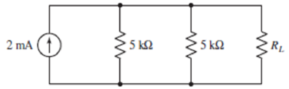
FIGURE 5.87
Expert Solution & Answer
Want to see the full answer?
Check out a sample textbook solution
Students have asked these similar questions
Homework:
Obtain vo in the circuit of the following figure.
5.3
30 V
20 V
4 k2
2 k2
3 k2
Answer
20 V
ww
5.52
What resistor connected between terminals a and h in the bridgc circuit shown in Fig. 5-53 absorbs maximum
power and what is this power!
Ans.
2.67 kN, 4.25 mW
2 kll
73.3 kfl
20 V
5 kn
2 kn
Fig. 5-53
and V
in terms of V,, V2, and R.
out2
5.6. For the following circuit, express Iout1
R
R
R
Voutz
Iouty
R
V1
V2
Chapter 5 Solutions
Loose Leaf for Engineering Circuit Analysis Format: Loose-leaf
Ch. 5.1 - For the circuit of Fig. 5.4, use superposition to...Ch. 5.2 - For the circuit of Fig. 5.7, use superposition to...Ch. 5.2 - For the circuit of Fig. 5.18, compute the current...Ch. 5.2 - For the circuit of Fig. 5.20, compute the voltage...Ch. 5.3 - Using repeated source transformations, determine...Ch. 5.3 - Use Thvenins theorem to find the current through...Ch. 5.3 - Determine the Thvenin and Norton equivalents of...Ch. 5.3 - Find the Thvenin equivalent for the network of...Ch. 5.3 - Find the Thvenin equivalent for the network of...Ch. 5.4 - Consider the circuit of Fig. 5.43. FIGURE 5.43...
Ch. 5.5 - Prob. 11PCh. 5 - Linear systems are so easy to work with that...Ch. 5 - Prob. 2ECh. 5 - Prob. 3ECh. 5 - (a) Employ superposition to determine the current...Ch. 5 - (a) Using superposition to consider each source...Ch. 5 - (a) Determine the individual contributions of each...Ch. 5 - (a) Determine the individual contributions of each...Ch. 5 - After studying the circuit of Fig. 5.53, change...Ch. 5 - Consider the three circuits shown in Fig. 5.54....Ch. 5 - (a) Using superposition, determine the voltage...Ch. 5 - Employ superposition principles to obtain a value...Ch. 5 - (a) Employ superposition to determine the...Ch. 5 - Perform an appropriate source transformation on...Ch. 5 - (a) For the circuit of Fig. 5.59, plot iL versus...Ch. 5 - Determine the current labeled I in the circuit of...Ch. 5 - Verify that the power absorbed by the 7 resistor...Ch. 5 - (a) Determine the current labeled i in the circuit...Ch. 5 - (a) Using repeated source transformations, reduce...Ch. 5 - Prob. 19ECh. 5 - (a) Making use of repeated source transformations,...Ch. 5 - Prob. 21ECh. 5 - (a) With the assistance of source transformations,...Ch. 5 - For the circuit in Fig. 5.67 transform all...Ch. 5 - Prob. 24ECh. 5 - (a) Referring to Fig. 5.69, determine the Thevenin...Ch. 5 - (a) With respect to the circuit depicted in Fig....Ch. 5 - (a) Obtain the Norton equivalent of the network...Ch. 5 - (a) Determine the Thevenin equivalent of the...Ch. 5 - Referring to the circuit of Fig. 5.71: (a)...Ch. 5 - Prob. 30ECh. 5 - (a) Employ Thvenins theorem to obtain a...Ch. 5 - Prob. 32ECh. 5 - Determine the Norton equivalent of the circuit...Ch. 5 - For the circuit of Fig. 5.75: (a) Employ Nortons...Ch. 5 - (a) Obtain a value for the Thvenin equivalent...Ch. 5 - Prob. 36ECh. 5 - Obtain a value for the Thvenin equivalent...Ch. 5 - With regard to the network depicted in Fig. 5.79,...Ch. 5 - Determine the Thvenin and Norton equivalents of...Ch. 5 - Determine the Norton equivalent of the circuit...Ch. 5 - Prob. 41ECh. 5 - Determine the Thvenin and Norton equivalents of...Ch. 5 - Prob. 43ECh. 5 - Prob. 44ECh. 5 - Prob. 45ECh. 5 - (a) For the simple circuit of Fig. 5.87, find the...Ch. 5 - For the circuit drawn in Fig. 5.88, (a) determine...Ch. 5 - Study the circuit of Fig. 5.89. (a) Determine the...Ch. 5 - Prob. 49ECh. 5 - Prob. 50ECh. 5 - With reference to the circuit of Fig. 5.91, (a)...Ch. 5 - Prob. 52ECh. 5 - Select a value for RL in Fig. 5.93 such that it...Ch. 5 - Determine what value of resistance would absorb...Ch. 5 - Derive the equations required to convert from a...Ch. 5 - Convert the - (or "-") connected networks in Fig....Ch. 5 - Convert the Y-(or T-) connected networks in Fig....Ch. 5 - For the network of Fig. 5.97, select a value of R...Ch. 5 - For the network of Fig. 5.98, select a value of R...Ch. 5 - Prob. 60ECh. 5 - Calculate Rin as indicated in Fig.5.100. FIGURE...Ch. 5 - Employ Y conversion techniques as appropriate to...Ch. 5 - Prob. 63ECh. 5 - (a) Use appropriate techniques to obtain both the...Ch. 5 - (a) For the network in Fig. 5.104, replace the...Ch. 5 - Prob. 66ECh. 5 - Prob. 67ECh. 5 - A 2.57 load is connected between terminals a and...Ch. 5 - A load resistor is connected across the open...Ch. 5 - A backup is required for the circuit depicted in...Ch. 5 - (a) Explain in general terms how source...Ch. 5 - The load resistor in Fig. 5.108 can safely...Ch. 5 - Prob. 74ECh. 5 - As part of a security system, a very thin 100 ...Ch. 5 - With respect to the circuit in Fig. 5.90, (a)...
Additional Engineering Textbook Solutions
Find more solutions based on key concepts
Design an ideal inverting op-amp circuit such that the voltage gain is Av=25 . The maximum current in any resis...
Microelectronics: Circuit Analysis and Design
Identify the type of input and output configuration for each diff-amp in Figure 18-35.
Electronics Fundamentals: Circuits, Devices & Applications
Three point charges of equal magnitude q, that will yield a zero net electric field at the origin.
Engineering Electromagnetics
When travelers from the USA and Canada visit Europe, they encounter a different power distribution system. Wall...
Electric machinery fundamentals
For the “tank” circuit in Fig. 14.79, find the resonant frequency.
Figure 14.79
For Probs. 14.39, 14.71, and 1...
Fundamentals of Electric Circuits
How many coulombs do 93.8 1016 electrons represent?
Principles Of Electric Circuits
Knowledge Booster


Learn more about
Need a deep-dive on the concept behind this application? Look no further. Learn more about this topic, electrical-engineering and related others by exploring similar questions and additional content below.Similar questions
- "NODAL VOLTAGE ANALYSIS" Please Find the Vo Using NODAL VOLTAGE ANALYSIS thankyou very much! I've included a cicruit app to check if your answer was correct and close to the value of currents and voltages which is 0.5V thankyou! I've been testing simple circuits to practice problems using different theorems,I appreciate you very much Thankyou!arrow_forwardHomework: Obtain vo in the circuit of the following figure. 5.3 30 V 20 V 4 kS2 2 k2 5 k2 Answer 20 Varrow_forwardUsing Kirchhoff's voltage law, find the unknown voltages for the configurations in Fig. 5.107. 20 V + V₁ - - IV + + 10 V ō +2V- www www - V₂ + 10 V + V₁ - www V₂ - 6V + +||| - 3V+ 2 Varrow_forward
- "SUPERPOSITION THEOREM" Please Find the Vo Using SUPERPOSITION THEOREM thankyou very much! I've included a cicruit app to check if your answer was correct and close to the value of currents and voltages which is 0.5V thankyou! I've been testing simple circuits to practice problems using different theorems,I appreciate you very much Thankyou!arrow_forward21/ Potential Divider Principle is the simplest way of producing a source of higher EMF from a source of lower EMF. Select one: True Falsearrow_forwardComponent values of the following circuit are listed in the Table I. Answer the following questions and provide your answers in Table II. a) using KCL equations, find resistance value at node c? Table I. Components R3 (0) 1 [rad/s] ww Vin 1 40° R₁ 1k [Ω] R₁ b R₂ a ww ww C R₂ 1k [Ω] R3 1k [22] kı 0.002 [A/V] k2 0.004 [A/V] Table II. Answer Vin k₁Vac k₂Vb Resistance at node carrow_forward
- Superposition V. Determine the current flowing through (Ix) and voltage across the 2 ohms resistor (Vx) a.) 3V acting alone a.1) Draw the circuit with 3v acting alone a.2) Solve to find Ix' and Vx' b.) 4A acting alone b.1) draw the circuit with 4A acting alone b.2) use circuit simulation software( NI Multisim, or Multisim live, or Everycircuit) simulate circuit (from b.1) and add properly ammeter and voltmeter to find Ix'' and Vx'' with 4A acting alone b.3.) Solve to find Ix'' and Vx'' (manually) c.) solve for Ix and Vx from results of (a.1, a.2, b.2) d.) simulate the original given circuit (with 3v and 4A) to check the results (from c, for Ix and Vx)arrow_forwardComponent values of the following circuit are listed in the Table I. Answer the following questions and provide your answers in Table II. a) using KCL equations, find resistance value at node c? Table I. Components 1 [rad/s] (0) R3 Vin 1 40° ww RI 1k [22] R₁ b R₂ C 1k [Ω] a ww 1k [Ω] 0.002 [A/V] 0.004 [A/V] k₁ Vac kzVb Resistance at node c R₂ R3 kı k2 Table II. Answerarrow_forwarda. Design the circuit in Fig. 5.117 such that VR₂ = 3VR, and VR₂ 4 VR₂ b. If the current is reduced to 10 μA, what are the new val- ues of R₁, R₂, and R3? How do they compare to the re- sults of part (a)? AL- = إسكان E 10 mA 4₁₁ www www R₁ R₂ 64 V R3 wwwarrow_forward
- Find I in the circuit shown in Fig. 5-48, which contains a nonlinear element having a V-{ relation of V = 3/². Use Thévenin's theorem and the quadratic formula. 5.45 Ans. 2 A 4 0 22 vE 9. V = 31' Fig. 5-48arrow_forward(True/False) It is safe to connect a 2002 resistor rated at 3/4W in parallel with a 10V source rated 10W. Select one: O True O Falsearrow_forwardFind the total resistance R, for each configuration in Fig. 5.86. Note that only standard resistor values were used. R R3 R3 R 0.39 kn 12 kn 1.20 2.7A RT R, (a) (b) R 82 kl 47A R 10kn R, {1 kn R4 Ry 1.8 n R.4, 820n R R, 12 kl 91 0 27 kn (c) (d) FIG. 5.86arrow_forward
arrow_back_ios
SEE MORE QUESTIONS
arrow_forward_ios
Recommended textbooks for you
 Introductory Circuit Analysis (13th Edition)Electrical EngineeringISBN:9780133923605Author:Robert L. BoylestadPublisher:PEARSON
 Delmar's Standard Textbook Of ElectricityElectrical EngineeringISBN:9781337900348Author:Stephen L. HermanPublisher:Cengage Learning
 Programmable Logic ControllersElectrical EngineeringISBN:9780073373843Author:Frank D. PetruzellaPublisher:McGraw-Hill Education
 Fundamentals of Electric CircuitsElectrical EngineeringISBN:9780078028229Author:Charles K Alexander, Matthew SadikuPublisher:McGraw-Hill Education
 Electric Circuits. (11th Edition)Electrical EngineeringISBN:9780134746968Author:James W. Nilsson, Susan RiedelPublisher:PEARSON
 Engineering ElectromagneticsElectrical EngineeringISBN:9780078028151Author:Hayt, William H. (william Hart), Jr, BUCK, John A.Publisher:Mcgraw-hill Education,
Introductory Circuit Analysis (13th Edition)
Electrical Engineering
ISBN:9780133923605
Author:Robert L. Boylestad
Publisher:PEARSON
Delmar's Standard Textbook Of Electricity
Electrical Engineering
ISBN:9781337900348
Author:Stephen L. Herman
Publisher:Cengage Learning
Programmable Logic Controllers
Electrical Engineering
ISBN:9780073373843
Author:Frank D. Petruzella
Publisher:McGraw-Hill Education
Fundamentals of Electric Circuits
Electrical Engineering
ISBN:9780078028229
Author:Charles K Alexander, Matthew Sadiku
Publisher:McGraw-Hill Education
Electric Circuits. (11th Edition)
Electrical Engineering
ISBN:9780134746968
Author:James W. Nilsson, Susan Riedel
Publisher:PEARSON
Engineering Electromagnetics
Electrical Engineering
ISBN:9780078028151
Author:Hayt, William H. (william Hart), Jr, BUCK, John A.
Publisher:Mcgraw-hill Education,
Z Parameters - Impedance Parameters; Author: Electrical Engineering Authority;https://www.youtube.com/watch?v=qoD4AoNmySA;License: Standard Youtube License