
Loose Leaf for Engineering Circuit Analysis Format: Loose-leaf
9th Edition
ISBN: 9781259989452
Author: Hayt
Publisher: Mcgraw Hill Publishers
expand_more
expand_more
format_list_bulleted
Concept explainers
Videos
Textbook Question
Chapter 5, Problem 65E
(a) For the network in Fig. 5.104, replace the leftmost Δ network with an equivalent T network. (b) Perform a computer simulation to verify that your answer is in fact equivalent. (Hint: Try adding a load resistor.)
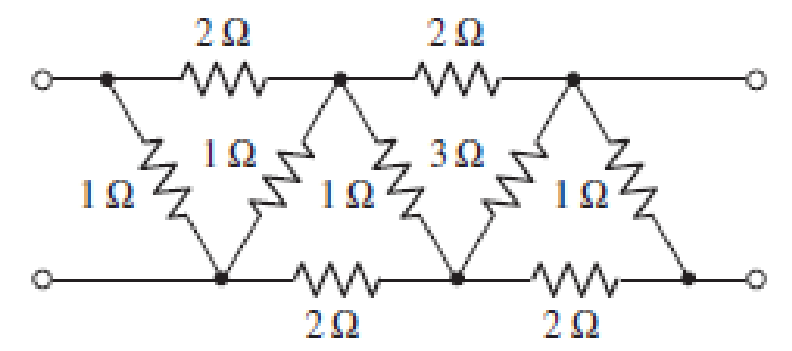
■ FIGURE 5.104
Expert Solution & Answer
Want to see the full answer?
Check out a sample textbook solution
Students have asked these similar questions
LMH_chapter3-part 1-homework [Protected View]
PowerPoint
ĐĂNG PHẠM HỒNG
File
Home
Insert
Design
Transitions
Animations
Slide Show
Review
View
Help
Tell me what you want to do
& Share
6.
HW18
5.20 In the circuit of Fig. 5.59, calculate v, of v; = 0.
HW20
8 ka
4
4 ka
5.32 Calculate iz and v, in the circuit of Fig. 5.70. Find
the power dissipated by the 30-kN resistor.
7
HW19
3.24 In the circuit shown in Fig 5.62, find k in the voltage
transfer flunction ,- ,
48 k2
ww
ww
8
4 mV
50 k2
HW20
60 k2
30 Ω
5.32 Calculate i, and e, in the circuit of Fig. 5.70. Find
the power dissipated by the 30 kl resistor
10 kΩ
4 mv (
50 ka
60
30 k2
10 k2
9.
HW21
5.33 Re:kn lo the p m tineuit in Fip 571 Caknulale4
ud the pomer disupated by dhe kil resistor.
1 kI
8
3 ma O
ww-
ww
LMH_chapter3-part 1-homework [Protected View]
PowerPoint
ĐĂNG PHẠM HỒNG
File
Home
Insert
Design
Transitions
Animations
Slide Show
Review
View
Help
Tell me what you want to do
& Share
4
HW16
5.13 Find u, and i, in the circuit of Fig. 5.52.
HW18
10 ka
1vO
100 ka
90 ka
10 ka
5.20 In the circuit of Fig. 5.59, calculate v, of v; = 0.
50 k2
8 kQ
HW17
ww
5.14 Determine the output voltage v, in the circuit of
5.53.
10 ka
2 k2
10 ka
20 ka
4 k2
4 k2
Sma O
5 kQ
www
ww
6.
9 V
HW18
5.20 In the circuit of Fig. 5.59, calculate v, of v; = 0.
8 ka
4 ka
4 ka
ww
7
HW19
3.24 In the circuit shown in Fig. 5.62, find k in the voltage
tYansfer flunction ,- b,
R.
6.
ww-
O
50
15. Why should design our circuits to operate below the SRF of electrical
elements?
to increase the gain
to make the circuit simple
None of them
to reduce the power used in the circuit.
to avoid the unexpected behavoir
Clear form
Page 1 of 1
Submit
Never submit passwords through Google Forms.
Chapter 5 Solutions
Loose Leaf for Engineering Circuit Analysis Format: Loose-leaf
Ch. 5.1 - For the circuit of Fig. 5.4, use superposition to...Ch. 5.2 - For the circuit of Fig. 5.7, use superposition to...Ch. 5.2 - For the circuit of Fig. 5.18, compute the current...Ch. 5.2 - For the circuit of Fig. 5.20, compute the voltage...Ch. 5.3 - Using repeated source transformations, determine...Ch. 5.3 - Use Thvenins theorem to find the current through...Ch. 5.3 - Determine the Thvenin and Norton equivalents of...Ch. 5.3 - Find the Thvenin equivalent for the network of...Ch. 5.3 - Find the Thvenin equivalent for the network of...Ch. 5.4 - Consider the circuit of Fig. 5.43. FIGURE 5.43...
Ch. 5.5 - Prob. 11PCh. 5 - Linear systems are so easy to work with that...Ch. 5 - Prob. 2ECh. 5 - Prob. 3ECh. 5 - (a) Employ superposition to determine the current...Ch. 5 - (a) Using superposition to consider each source...Ch. 5 - (a) Determine the individual contributions of each...Ch. 5 - (a) Determine the individual contributions of each...Ch. 5 - After studying the circuit of Fig. 5.53, change...Ch. 5 - Consider the three circuits shown in Fig. 5.54....Ch. 5 - (a) Using superposition, determine the voltage...Ch. 5 - Employ superposition principles to obtain a value...Ch. 5 - (a) Employ superposition to determine the...Ch. 5 - Perform an appropriate source transformation on...Ch. 5 - (a) For the circuit of Fig. 5.59, plot iL versus...Ch. 5 - Determine the current labeled I in the circuit of...Ch. 5 - Verify that the power absorbed by the 7 resistor...Ch. 5 - (a) Determine the current labeled i in the circuit...Ch. 5 - (a) Using repeated source transformations, reduce...Ch. 5 - Prob. 19ECh. 5 - (a) Making use of repeated source transformations,...Ch. 5 - Prob. 21ECh. 5 - (a) With the assistance of source transformations,...Ch. 5 - For the circuit in Fig. 5.67 transform all...Ch. 5 - Prob. 24ECh. 5 - (a) Referring to Fig. 5.69, determine the Thevenin...Ch. 5 - (a) With respect to the circuit depicted in Fig....Ch. 5 - (a) Obtain the Norton equivalent of the network...Ch. 5 - (a) Determine the Thevenin equivalent of the...Ch. 5 - Referring to the circuit of Fig. 5.71: (a)...Ch. 5 - Prob. 30ECh. 5 - (a) Employ Thvenins theorem to obtain a...Ch. 5 - Prob. 32ECh. 5 - Determine the Norton equivalent of the circuit...Ch. 5 - For the circuit of Fig. 5.75: (a) Employ Nortons...Ch. 5 - (a) Obtain a value for the Thvenin equivalent...Ch. 5 - Prob. 36ECh. 5 - Obtain a value for the Thvenin equivalent...Ch. 5 - With regard to the network depicted in Fig. 5.79,...Ch. 5 - Determine the Thvenin and Norton equivalents of...Ch. 5 - Determine the Norton equivalent of the circuit...Ch. 5 - Prob. 41ECh. 5 - Determine the Thvenin and Norton equivalents of...Ch. 5 - Prob. 43ECh. 5 - Prob. 44ECh. 5 - Prob. 45ECh. 5 - (a) For the simple circuit of Fig. 5.87, find the...Ch. 5 - For the circuit drawn in Fig. 5.88, (a) determine...Ch. 5 - Study the circuit of Fig. 5.89. (a) Determine the...Ch. 5 - Prob. 49ECh. 5 - Prob. 50ECh. 5 - With reference to the circuit of Fig. 5.91, (a)...Ch. 5 - Prob. 52ECh. 5 - Select a value for RL in Fig. 5.93 such that it...Ch. 5 - Determine what value of resistance would absorb...Ch. 5 - Derive the equations required to convert from a...Ch. 5 - Convert the - (or "-") connected networks in Fig....Ch. 5 - Convert the Y-(or T-) connected networks in Fig....Ch. 5 - For the network of Fig. 5.97, select a value of R...Ch. 5 - For the network of Fig. 5.98, select a value of R...Ch. 5 - Prob. 60ECh. 5 - Calculate Rin as indicated in Fig.5.100. FIGURE...Ch. 5 - Employ Y conversion techniques as appropriate to...Ch. 5 - Prob. 63ECh. 5 - (a) Use appropriate techniques to obtain both the...Ch. 5 - (a) For the network in Fig. 5.104, replace the...Ch. 5 - Prob. 66ECh. 5 - Prob. 67ECh. 5 - A 2.57 load is connected between terminals a and...Ch. 5 - A load resistor is connected across the open...Ch. 5 - A backup is required for the circuit depicted in...Ch. 5 - (a) Explain in general terms how source...Ch. 5 - The load resistor in Fig. 5.108 can safely...Ch. 5 - Prob. 74ECh. 5 - As part of a security system, a very thin 100 ...Ch. 5 - With respect to the circuit in Fig. 5.90, (a)...
Knowledge Booster


Learn more about
Need a deep-dive on the concept behind this application? Look no further. Learn more about this topic, electrical-engineering and related others by exploring similar questions and additional content below.Similar questions
- Q17. For the circuit shown in Figure 5.23 calculate (a) the value of resistor Rx such that the total power dissipated in the circuit is 2.5kW, and (b) the current flowing in each of the four resistors. 4 Rq=15 2 a A3=38 2 R2=10 2 Rx 12 14 V2² 250 Varrow_forwardDesign a charger circuit for mobile phone from:1.5 V AA BatterySelect the proper circuit topologies and components. (please explain in detail)arrow_forwardConsider a 2.5kW PV system exposed to sun for 6 hours with the solar intensity of 1 sun. Calculate the total PV power generation for 3 years. Also, calculate the loss in PV power generation if the solar intensity is reduced to 0.8 sun and 0.5 sun. [Estimated time to solve: 8 min]arrow_forward
- Given the circuit below. The current through the 100 resistor in the circuit below is 8.0 mA. Determine the 2002 5.0 (2 [www] 10:2 a) total resistance b) total current c) total voltage 30 2 www wwww 5.002 4002arrow_forward6:06 A e-learning.hct.edu.om Question: A group of Students from UTAS (Physics Unit) visit Al Hassan Electrical laboratory. Their supervisor gives them instruction about use of Resistors in different electrical appliances. Students are provided with four resistors R,=50 ohm, R2=70 ohm, R3=380 ohm, R4=70 ohm and a battery of 40 v. i) If students connect these four resistances in series, what is the effective resistance? ii) If students connect these four resistances in parallel, what is the effective resistance? iii) If students connect 40 V battery across series combination, what is the current flowing in the circuit? iv) If students connect 40 V battery across parallel combination, what is the current flowing in the circuit? v) If students connect these four resistances shown below, what is the voltage across points a and d? R2 R1 R4 b. R3 V Finish attempt...arrow_forwardExplain in detail the difference between a Micro-Electronics / Photonics Engineer and an Electronic Circuit Design Engineer. Be specific and provide details. Please cite all your sources. • Could these engineers have projects in common? Give examples answer all twoarrow_forward
- show your complete solution. need asaparrow_forwardQ:Discuss the following arguments: 1)Different types of consumers should effectivelyparticipateto realize smart grids 2)Capacitorsusually have both high power densities and energystorage capabilities. ****** Please solve the question correctly and if you are not sure of the answer tell mearrow_forwardState which of the following statements are true and which are false. Give reasons for youranswers.a) A very simple circuit consists of a battery connected across a resistor. In this circuit, thebattery and the resistor are both in series and also in parallel.b) A resistor R and a capacitor C connected in series combine as 1RC =1R +1Cc) Natural uranium is not radioactive until it has been processed by enrichment for use infission reactors or bombs.d) Infrared light is more likely to cause electrons to be emitted from a metal than ultravioletlight.e) Special and General Relativity effects both matter for the operation of GPS, the former slowing down the clocks on GPS satellites relative to clocks on Earth and the latter speedingthem up.arrow_forward
- Answer the following problem (Kindly provide a CLEAR and COMPLETE solution)*Note: Please answer it ASAP if possible*arrow_forwardIn the node-voltage method, when a dependent voltage source connects two essential nodes, how can this situation be handled? A. The dependent source and its two ends are treated as a supernode for which a single KCL equation can be written. B. The two essential nodes are temporarily treated as having the same voltage. C. The dependent source is temporarily treated as an open circuit. D. The KCL equation is written for only one of the two essential nodes, and a KCL equation is written for the reference node. E. None of the provided options.arrow_forward5.2 For the circuit of Fig. 5.7, use superposition to obtain the voltage across each current source. Ans: Viha = 9.180 V, v2zA =-1.148 V, UIlay = 1.967 V, v2by = -0.246 V; vI = 11.147 V, vz = -1.394 V. %3D %3D %3D 15 N 12 4i 2 A( 3 Varrow_forward
arrow_back_ios
SEE MORE QUESTIONS
arrow_forward_ios
Recommended textbooks for you
 Introductory Circuit Analysis (13th Edition)Electrical EngineeringISBN:9780133923605Author:Robert L. BoylestadPublisher:PEARSON
 Delmar's Standard Textbook Of ElectricityElectrical EngineeringISBN:9781337900348Author:Stephen L. HermanPublisher:Cengage Learning
 Programmable Logic ControllersElectrical EngineeringISBN:9780073373843Author:Frank D. PetruzellaPublisher:McGraw-Hill Education
 Fundamentals of Electric CircuitsElectrical EngineeringISBN:9780078028229Author:Charles K Alexander, Matthew SadikuPublisher:McGraw-Hill Education
 Electric Circuits. (11th Edition)Electrical EngineeringISBN:9780134746968Author:James W. Nilsson, Susan RiedelPublisher:PEARSON
 Engineering ElectromagneticsElectrical EngineeringISBN:9780078028151Author:Hayt, William H. (william Hart), Jr, BUCK, John A.Publisher:Mcgraw-hill Education,
Introductory Circuit Analysis (13th Edition)
Electrical Engineering
ISBN:9780133923605
Author:Robert L. Boylestad
Publisher:PEARSON
Delmar's Standard Textbook Of Electricity
Electrical Engineering
ISBN:9781337900348
Author:Stephen L. Herman
Publisher:Cengage Learning
Programmable Logic Controllers
Electrical Engineering
ISBN:9780073373843
Author:Frank D. Petruzella
Publisher:McGraw-Hill Education
Fundamentals of Electric Circuits
Electrical Engineering
ISBN:9780078028229
Author:Charles K Alexander, Matthew Sadiku
Publisher:McGraw-Hill Education
Electric Circuits. (11th Edition)
Electrical Engineering
ISBN:9780134746968
Author:James W. Nilsson, Susan Riedel
Publisher:PEARSON
Engineering Electromagnetics
Electrical Engineering
ISBN:9780078028151
Author:Hayt, William H. (william Hart), Jr, BUCK, John A.
Publisher:Mcgraw-hill Education,
Z Parameters - Impedance Parameters; Author: Electrical Engineering Authority;https://www.youtube.com/watch?v=qoD4AoNmySA;License: Standard Youtube License