
Concept explainers
Videos
8–37 to
8–40 Repeat the requirements for the problem specified in the table if the bolts and nuts are replaced with cap screws that are threaded into tapped holes in the cast-iron cylinder.
| Problem Number | Originating Problem Number |
| 8–37 | 8–33 |
| 8–38 | 8–34 |
| 8–39 | 8–35 |
| 8–40 | 8–36 |
8–33 to
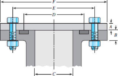
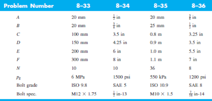
8–36 The figure illustrates the non-permanent connection of a steel cylinder head to a grade 30 castiron pressure vessel using N bolts. A confined gasket seal has an effective sealing diameter D. The cylinder stores gas at a maximum pressure pg. For the specifications given in the table for the specific problem assigned, select a suitable bolt length from the preferred sizes in Table A–17, then determine the yielding factor of safety np, the load factor nL, and the joint separation factor n0.
Repeat the requirements for the problem specified in the table if the bolts and nuts are replaced with cap screws that are threaded into tapped holes in the cast-iron cylinder.
Want to see the full answer?
Check out a sample textbook solution
Chapter 8 Solutions
Shigley's Mechanical Engineering Design (McGraw-Hill Series in Mechanical Engineering)


- Figure below shows a portion of a pump that is gear-driven at uniform load and speed. The 25 mm diameter solod shaft supported by the bearings is to be made of machined AISI 1045 CD steel. The helical gear is subjected to the axial force F-498 y a radial load F- 750 N and a tangential load of F-1.995 N. Assume the component is g at room temperature of 70F and the material has s0s reliability factor. Hint: Be careful when you calculate the bending moment at the fillet, as all the three forces on the helical gear cause bending moment at the fillet. Calculate resultant bedina moment from all the three forces. Bending moment is completely reversed loading.) 25-mm solid round shaft Fillet Bending K, = 2.0 Torsional k, = 1.5 Axial K,18 F. F, F Pump Helical spur gear -50 mm -250-mm dia FIGURE 1. Identify the critical locations) of stress and show it clearly in a diagram. 2 Identity cleary, all the components of stresses (at the critical point) that will be calcurated (by drawing and clearty…arrow_forwardCalculate the dimensions of the I-section of a connecting rod, stating any assumptions. using the data below: Maximum cylinder pressure = 3.15N/mm² Cylinder bore = 100mm Factor of Safety=6 Crank length 95mm Connecting rod length=380mm Take the constant a=7500.arrow_forwardThe figure shows a schematic drawing of a vehicular jack that is to be designed to support a maximum mass of 300 kg based on the use of a design factor na = 3.50. The opposite-handed threads on the two ends of the screw are cut to allow the link angle 0 to vary from 15 to 70°. The links are to be machined from AISI 1010 hot-rolled steel bars. Each of the four links is to consist of two bars, one on each side of the central bearings. The bars are to be 350 mm long and have a bar width of w = 30 mm. The pinned ends are to be designed to secure an end-condition constant of at least C = 1.4 for out-of-plane buckling. Find a suitable preferred thickness and the resulting factor of safety for this thickness. W 華 warrow_forward
- The figure illustrates the connection of a steel cylinder head to a grade 30 cast-iron pressure vessel using N bolts. A confined gasket seal has an effective sealing diameter D. The cylinder stores gas at a maximum pressure pg. For the specifications given in the table for the specific problem assigned, select a suitable bolt length from the preferred sizes in Table A–17, then determine the yielding factor of safety np, the load factor nL, and the joint separation factor n0. See problem number 8-36, and please use the FEA exponential curve-fit for member stiffness.arrow_forwardThe chain drive is mounted in the center for the system shown in figure.It can transmit 15 hp at a speed of 400 rpm and the sprocket has a pitch diameter of 6 inches. The shaft is made of ASTM-A 709 Grade 50 steel. A factor of safety of 2.5 is required. Is the design acceptable? Hint: You need to calculate torsion and bending stresses during solution.arrow_forwardThe rotating shaft shown in the figure is machined from AISI 1040 CD steel (sy = 490 MPa, Sut = 590 MPa). It is subjected to a transverse force of F = 8 kN between the supports. The system designed to be operated at a temperature of 120°C with a reliability of 99%. Estimate the number of cycles to failure. All dimensions are in mm. Assume all fillets are 3mm in radius. 25 D. 20 20 -35 D. 180- 3 R. 500 F 280 -175- -50 D. 25 D. | ª -20 20arrow_forward
- 8-75 A vertical channel 152 X 76 (see Table A–7) has a cantilever beam bolted to it as shown. The channel is hot-rolled AISI 1006 steel. The bar is of hot-rolled AISI 1015 steel. The shoulder bolts are M10 × 1.5 ISO 5.8. Assume the bolt threads do not extend into the joint. For a design factor of 2.0, find the safe force F that can be applied to the cantilever. 8T-8 12 Problem 8-75 in millimeters. 50 -50→-50→261! 125 000arrow_forwardThe figure shows a shaft mounted in bearings at A and D and having pulleys at B and C. The forces shown acting on the pulley surfaces represent the belt tensions. The shaft is to be made of ASTM grade 25 cast iron using a design factor na = 2.8. What diameter should be used for the shaft? 6-in D. 300 lbf 27 lbf 360 lbf D 6 in A 8 in 50 lbf B 8-in D. 8 inarrow_forwardSolve the following problems as stated below. Draw the figure and FBD. PROBLEM A flanged bolt coupling consist of 9 steel bolts evenly spaced around a bolt circle 300 mm. in diameter and 6 bronze bolts on a concentric bplt circle 200 mm. in diameter. What are the sizes of bolts diameters for steel and bronze, if the torque applied is 6,000 N-m and without exceeding the stress of 60 MPa in the steel and 40 MPa for the bronze? The ratio of the bolt diameter dp / ds = 0.50. For steel, use Gs = 83 GPa and for bronze, Gp = 28 Gpa. R Rs Rbarrow_forward
- Required information The shaft shown in the figure is machined from AISI 1040 CD steel. The shaft rotates at 1600 rpm and is supported in rolling bearings at A and B. The applied forces are F₁ = 800 lbf and F2=1200 lbf. Determine the minimum fatigue factor of safety based on achieving infinite life. If infinite life is not predicted, estimate the number of cycles to failure. Also check for yielding -10 in- -10 is -fim All Gillets in R. What are the values of the theoretical stress-concentration factor, the notch sensitivity, and the fatigue stress-concentration factor? The value of the theoretical stress concentration-factor is The value of the notch sensitivity is. The value of the fatigue stress concentration-factor is [arrow_forwardThe pedal system shown in the figure is exerted by both an up and down mechanism. These forces are Fmax=350*SN/10 N, Fmin=-150*SN/10 N. It is desired that h/b = 5 seen in the figure. This piece is AISI 1040 and has a maximum tensile stress of 670Mpa and a yield stress of 540Mpa. Known weakening factors are known as kb=ky=kd=0.8. The notch factor for all stresses is assumed to be Kç=1.5. It is desired to last up to its minimum indefinite life at the cross-section measurement point (bxh) shown in the figure. According to Goodman theory, what should be the minimum size (b and h value) of this section in order to meet this condition. SN=89arrow_forwardThe value of curvature correction factor k, will be if the spring index is 6. O a. 1.33 O b. 1.08 O c. 0.92 O d. 4.00 The figure below shows the components of normal forces, the value of radial force on the gear wheel due to a tangential force of 642 N is N, Take pressure angle as 14½0. at Pitch P. point Gear driven to 02 The radial force isarrow_forward
 Mechanics of Materials (MindTap Course List)Mechanical EngineeringISBN:9781337093347Author:Barry J. Goodno, James M. GerePublisher:Cengage Learning