
Shigley's Mechanical Engineering Design (McGraw-Hill Series in Mechanical Engineering)
10th Edition
ISBN: 9780073398204
Author: Richard G Budynas, Keith J Nisbett
Publisher: McGraw-Hill Education
expand_more
expand_more
format_list_bulleted
Concept explainers
Videos
Textbook Question
Chapter 8, Problem 71P
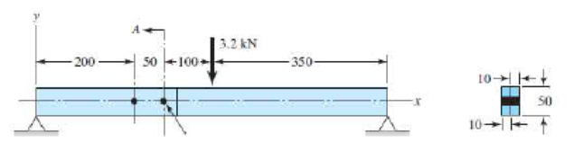
A beam is made up by bolting together two cold drawn bars of AISI 1018 steel as a lap joint, as shown in the figure. The bolts used are ISO 5.8. Assume the bolt threads do not extend into the joint. Ignoring any twisting, determine the factor of safety of the connection.
Problem 8–71 Dimensions in millimeters.
Expert Solution & Answer
Want to see the full answer?
Check out a sample textbook solution
Students have asked these similar questions
Two plates are clamped by a 3/4-10 UNC SAE
Grade 5 bolt and regular nut with a 3/4-W plain
washer as shown in figure. Top plate is made of
grey cast iron and bottom plate is steel. An axial
force of 12kN is acted upon the joint. Round off
the length of the bolt to nearest 1/4in. Assume
bolts are preloaded to 75% of proof load.
1. Determine the bolt stiffness kb.
2. Determine the member stiffness km.
3. Determine the yielding factor of safety of the
bolt.
4. Determine the load factor for the bolt.
5. Determine the load factor guarding against
joint separation.
1.25 in
1.00 in
The figure gives the cross-section of a grade 25 cast-iron pressure vessel. A total of N bolts are to be used to resist a separating force of 150 kN.
(a) Determine kb, km, and C.
(b) Find the number of bolts required for a load factor of 2 where the bolts may be reused when the joint is taken apart.
(c) With the number of bolts obtained in part (b), determine the realized load factor for overload, the yielding factor of safety, and the load factor for joint separation.
Use (SI) units as it applies
Solve the following problems as stated below. Draw the figure and FBD.
PROBLEM
A flanged bolt coupling consist of 9 steel bolts evenly spaced around a bolt
circle 300 mm. in diameter and 6 bronze bolts on a concentric bplt circle 200 mm.
in diameter. What are the sizes of bolts diameters for steel and bronze, if the
torque applied is 6,000 N-m and without exceeding the stress of 60 MPa in the
steel and 40 MPa for the bronze? The ratio of the bolt diameter dp / ds = 0.50. For
steel, use Gs = 83 GPa and for bronze, Gp = 28 Gpa.
R
Rs
Rb
Chapter 8 Solutions
Shigley's Mechanical Engineering Design (McGraw-Hill Series in Mechanical Engineering)
Ch. 8 - A power screw is 25 mm in diameter and has a...Ch. 8 - Using the information in the footnote of Table...Ch. 8 - Show that for zero collar friction the efficiency...Ch. 8 - A single-threaded power screw is 25 mm in diameter...Ch. 8 - The machine shown in the figure can be used for a...Ch. 8 - The press shown for Prob. 8-5 has a rated load of...Ch. 8 - For the screw clamp shown, a force is applied at...Ch. 8 - The C clamp shown in the figure for Prob. 8-7 uses...Ch. 8 - Find the power required to drive a 1.5-in power...Ch. 8 - A single square-thread power screw has an input...
Ch. 8 - Prob. 11PCh. 8 - An M14 2 hex-head bolt with a nut is used to...Ch. 8 - Prob. 13PCh. 8 - A 2-in steel plate and a 1-in cast-iron plate are...Ch. 8 - Repeat Prob. 8-14 with the addition of one 12 N...Ch. 8 - A 2-in steel plate and a 1-in cast-iron plate are...Ch. 8 - Two identical aluminum plates are each 2 in thick,...Ch. 8 - Prob. 18PCh. 8 - A 30-mm thick AISI 1020 steel plate is sandwiched...Ch. 8 - Prob. 20PCh. 8 - Prob. 21PCh. 8 - Prob. 22PCh. 8 - A 2-in steel plate and a 1-in cast-iron plate are...Ch. 8 - An aluminum bracket with a 12-in thick flange is...Ch. 8 - An M14 2 hex-head bolt with a nut is used to...Ch. 8 - A 34 in-16 UNF series SAE grade 5 bolt has a 34-in...Ch. 8 - From your experience with Prob. 8-26, generalize...Ch. 8 - Prob. 28PCh. 8 - Prob. 29PCh. 8 - Prob. 30PCh. 8 - For a bolted assembly with eight bolts, the...Ch. 8 - Prob. 32PCh. 8 - 8-33 to 8-36 The figure illustrates the...Ch. 8 - 8-33 to 8-36 The figure illustrates the...Ch. 8 - 8-33 to 8-36 The figure illustrates the...Ch. 8 - 8-33 to 8-36 The figure illustrates the...Ch. 8 - Prob. 37PCh. 8 - Prob. 38PCh. 8 - 837 to 840 Repeat the requirements for the problem...Ch. 8 - Prob. 40PCh. 8 - 841 to 844 For the pressure vessel defined in the...Ch. 8 - Prob. 42PCh. 8 - Prob. 43PCh. 8 - Prob. 44PCh. 8 - Bolts distributed about a bolt circle are often...Ch. 8 - The figure shows a cast-iron bearing block that is...Ch. 8 - Prob. 47PCh. 8 - Prob. 48PCh. 8 - Prob. 49PCh. 8 - Prob. 50PCh. 8 - 851 to 854 For the pressure cylinder defined in...Ch. 8 - Prob. 52PCh. 8 - 851 to 854 For the pressure cylinder defined in...Ch. 8 - 851 to 854 For the pressure cylinder defined in...Ch. 8 - 855 to 858 For the pressure cylinder defined in...Ch. 8 - 855 to 858 For the pressure cylinder defined in...Ch. 8 - 855 to 858 For the pressure cylinder defined in...Ch. 8 - For the pressure cylinder defined in the problem...Ch. 8 - A 1-in-diameter hot-rolled AISI 1144 steel rod is...Ch. 8 - The section of the sealed joint shown in the...Ch. 8 - Prob. 61PCh. 8 - Prob. 62PCh. 8 - Prob. 63PCh. 8 - Prob. 64PCh. 8 - Using the Goodman fatigue criterion, repeat Prob....Ch. 8 - The figure shows a bolted lap joint that uses SAE...Ch. 8 - Prob. 67PCh. 8 - A bolted lap joint using ISO class 5.8 bolts and...Ch. 8 - Prob. 69PCh. 8 - The figure shows a connection that employs three...Ch. 8 - A beam is made up by bolting together two cold...Ch. 8 - Prob. 72PCh. 8 - Prob. 73PCh. 8 - Prob. 74PCh. 8 - A vertical channel 152 76 (see Table A7) has a...Ch. 8 - The cantilever bracket is bolted to a column with...Ch. 8 - Prob. 77PCh. 8 - The figure shows a welded fitting which has been...Ch. 8 - Prob. 79PCh. 8 - Prob. 80PCh. 8 - Prob. 81P
Knowledge Booster


Learn more about
Need a deep-dive on the concept behind this application? Look no further. Learn more about this topic, mechanical-engineering and related others by exploring similar questions and additional content below.Similar questions
- An inflatable structure used by a traveling circus has the shape of a half-circular cylinder with closed ends (see figure). The fabric and plastic structure is inflated by a small blower and has a radius of 40 ft when fully inflated. A longitudinal scam runs the entire length of the "ridge" of the structure. If the longitudinal scam along the ridge tears open when it is subjected to a tensile load of 540 pounds per inch of seam, what is the factor of safety n against tearing when the internal pressure is 0,5 psi and the structure is fully inflated?arrow_forwardRepeat Problem 11.2-3 assuming that R= 10 kN · m/rad and L = 2 m.arrow_forwardA vertical channel 152 x 76 (see Table A-7) has a cantilever beam bolted to it as shown. The channel is hot-rolled AISI 1006 steel. The bar is of hot-rolled AISI 1015 steel. The shoulder bolts are M10 x 1.5 ISO 5.8. Assume the bolt threads do not extend into the joint. For a design factor of 2.2, find the safe force Fthat can be applied to the cantilever. 12 50 +50--50-- 26! 125 The maximum allowable force on the system Fis N.arrow_forward
- Solve the following problems as stated below. Draw the figure and FBD. PROBLEM A flanged bolt coupling consist of 9 steel bolts evenly spaced around a bolt circle 300 mm. in diameter and 6 bronze bolts on a concentric bplt circle 200 mm. in diameter. What are the sizes of bolts diameters for steel and bronze, if the torque applied is 6,000 N-m and without exceeding the stress of 60 MPa in the steel and 40 MPa for the bronze? The ratio of the bolt diameter d, / ds = 0.50. For steel, use Gs = 83 GPa and for bronze, G, = 28 Gpa. %3D Rs Rparrow_forward3- Select an unequal -leg angle tension member 15 feet long to resist a service dead load of 35 kips and a service live load of 70 kips. Use A36 steel. The connection is shown in figure. 3/4 in-diameter boltsarrow_forwardThe figure shows a schematic drawing of a vehicular jack that is to be designed to support a maximum mass of 300 kg based on the use of a design factor na = 3.50. The opposite-handed threads on the two ends of the screw are cut to allow the link angle 0 to vary from 15 to 70°. The links are to be machined from AISI 1010 hot-rolled steel bars. Each of the four links is to consist of two bars, one on each side of the central bearings. The bars are to be 350 mm long and have a bar width of w = 30 mm. The pinned ends are to be designed to secure an end-condition constant of at least C = 1.4 for out-of-plane buckling. Find a suitable preferred thickness and the resulting factor of safety for this thickness. W 華 warrow_forward
- Problem 7: Analyse to determine the maximum service tensile live load force that can be supported by a pair of angles 2Ls 152x102x19, shown in the accompanying figure, if 4709M, Grade 345 steel and the AISC LRFD specifications are used. The live load is to be 3/2 times the dead load. The holes are drilled for 18mm rivets at standard gage distances.arrow_forwardLink 2, shown in the figure, is 25 mm wide and 11 mm thick. It is made from low-carbon steel with Sy= 165 MPa. The pin joints are constructed with sufficient size and fit to provide good resistance to out-of-plane bending. Use Table 4-2 shown below for recommended values for C. Determine the following for link 2: a.)Axial Force b.)Yield factor of safety c.) In-plane buckling factor of safety and Out-plane buckling factor of safetyarrow_forwardProblem 3: A Hexagonal bolt connects two members. The joint has a gap 1 = 2 in and the applied load is 2000 lb. Both of the clamped parts are steel. A preload of 90% the bolt's proof strength will be applied first. For this design, an SAE grade 1, 5/16"-18 UNC-2A bolt is chosen made from A307 with rolled threads. Washers are included between the head and the joint, and between the nut and the joint. Determine a suitable length for the bolt? Find its safety factor against yielding and against joint separation. Are these values acceptable?arrow_forward
- 8-75 A vertical channel 152 X 76 (see Table A–7) has a cantilever beam bolted to it as shown. The channel is hot-rolled AISI 1006 steel. The bar is of hot-rolled AISI 1015 steel. The shoulder bolts are M10 × 1.5 ISO 5.8. Assume the bolt threads do not extend into the joint. For a design factor of 2.0, find the safe force F that can be applied to the cantilever. 8T-8 12 Problem 8-75 in millimeters. 50 -50→-50→261! 125 000arrow_forward3. An M16 x 2 bolt with a slotted hex nut is used to clamp together two 25 mm steel plates. The joint is assembled with a size 16 N washer underneath the bolt head. The bolt is a 5.8 class metric grade, with a proof strength of 380 MPa. The joint is intended to be permanent. Determine a suitable length for the bolt, rounded up to the nearest standard size in millimeters. Calculate the bolt stiffness, the elongation of the bolt after the necessary preload is developed, and the bolt torque required to apply the preload. Assume that coefficients of friction between the bolt, nut, and collar are all ~0.15. For steel, use E = 207 GPa. Standard threaded fastener lengths, dimensions of hexagonal nuts, and dimensions of metric plain washers are provided in the textbook appendices.arrow_forwardQestion-1: A 9/16 in UNF bolt is subjected to a load P = 60 kip in a tension joint as shown in Figure. The bolt is SAE grade 5 and lubricated. The initial bolt tension (F) = 35 kip. The bolt and joint stiffnesses are k, = 6.5 and km 10.8 Mlbf/in Note: Use the related tables, formulas and concepts to answer following question (a) Formulate to determine the preload and service load stresses in the bolt. (b) Solve to find the torque necessary to develop the preload. (c) Identify if the bolt will fail or no under preload and service load stresses (Calculated in part a) by comparing with the SAE minimum proof strength of the bolt. (d) Can you identify; with given input data, tables and formulas that bolt is self-locking? Table 8-9 SAE Specifications for Steel Bolts Size SAE Range Grade Inclusive, No. in +14 1 2 4 5 5.2 7 8 TI I LI I I I +-14 8.2 -1 Minimum Proof Strength," kpsi 33 55 33 65 85 74 85 105 120 120 Table 8-2 Diameters and Area of Unified Screw Threads Size Designation 0 1 2 3 4…arrow_forward
arrow_back_ios
SEE MORE QUESTIONS
arrow_forward_ios
Recommended textbooks for you
 Mechanics of Materials (MindTap Course List)Mechanical EngineeringISBN:9781337093347Author:Barry J. Goodno, James M. GerePublisher:Cengage Learning
Mechanics of Materials (MindTap Course List)
Mechanical Engineering
ISBN:9781337093347
Author:Barry J. Goodno, James M. Gere
Publisher:Cengage Learning
Engineering Basics - Statics & Forces in Equilibrium; Author: Solid Solutions - Professional Design Solutions;https://www.youtube.com/watch?v=dQBvQ2hJZFg;License: Standard YouTube License, CC-BY