
Shigley's Mechanical Engineering Design (McGraw-Hill Series in Mechanical Engineering)
10th Edition
ISBN: 9780073398204
Author: Richard G Budynas, Keith J Nisbett
Publisher: McGraw-Hill Education
expand_more
expand_more
format_list_bulleted
Concept explainers
Videos
Textbook Question
Chapter 8, Problem 7P
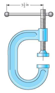
For the screw clamp shown, a force is applied at the end of the handle
- (a) What screw torque will cause the handle to bend permanently?
- (b) What clamping force will the answer to part (a) cause if the collar friction is neglected and if the thread friction is 0.15?
- (c) What clamping force will cause the screw to buckle?
- (d) Are there any other stresses or possible failures to be checked?
Problem 8-7
Expert Solution & Answer
Want to see the full answer?
Check out a sample textbook solution
Students have asked these similar questions
3 in
2. For the C-clamp shown in Fig.1 , a perpendicular force is applied (into
the page) at the end of the handle 3.5" from the centerline of the clamp
screw. The handle has a diameter D= 1/2" and is made of AISI 1035 CD
steel with a yield strength S, = 67 kpsi. The clamp screw is a 5/8 in–18
UNF, with ACME threads. Knowing that the maximum stress in the handle
will occur at the location where the handle protrudes from the screw
housing, what value of applied screw torque will cause the handle to bend
permanently when the clamp is fully closed? What clamp force corresponds
to this? Assume that collar friction is negligible and that the coefficient of
friction between the threads and the nut is 0.15.
Fig. 1
4) Ball bearings support the rotating axle shown below at points A and D. The rotating axle is loaded by
a stationary (non-rotating) force of F = 6.8 kN. In the drawing below, all dimensions are in mm, and
all geometry changes (steps in the diameter shaft) have a fillet radius of 3 mm. The axle is machined
from AISI cold-drawn steel with an ultimate strength of S_u = 690 MPa and a yield strength of S_y=
580 MPa. Calculate the safety factor at the 6.8 kN load and points B and C, which experience
moderate bending moments with a geometric feature that causes a stress concentration. Determine
the number of cycles to failure of this part.
30
-10
-250
32
B
6.8 KN
75
-38
100-
с
125
10
35
D
30
Bearing stress
4. Please provide proper discussion and illustration also complete solution and clear solution please thank you
Determine the length of a square key to be used for a 3.73 kW, 1800 rpm electric motor if the motor shaft diameter is 35 mm and the width of the key is approximately one-fourth of the shaft diameter. The allowable shearing stress on the key is 2.45 MPa
Chapter 8 Solutions
Shigley's Mechanical Engineering Design (McGraw-Hill Series in Mechanical Engineering)
Ch. 8 - A power screw is 25 mm in diameter and has a...Ch. 8 - Using the information in the footnote of Table...Ch. 8 - Show that for zero collar friction the efficiency...Ch. 8 - A single-threaded power screw is 25 mm in diameter...Ch. 8 - The machine shown in the figure can be used for a...Ch. 8 - The press shown for Prob. 8-5 has a rated load of...Ch. 8 - For the screw clamp shown, a force is applied at...Ch. 8 - The C clamp shown in the figure for Prob. 8-7 uses...Ch. 8 - Find the power required to drive a 1.5-in power...Ch. 8 - A single square-thread power screw has an input...
Ch. 8 - Prob. 11PCh. 8 - An M14 2 hex-head bolt with a nut is used to...Ch. 8 - Prob. 13PCh. 8 - A 2-in steel plate and a 1-in cast-iron plate are...Ch. 8 - Repeat Prob. 8-14 with the addition of one 12 N...Ch. 8 - A 2-in steel plate and a 1-in cast-iron plate are...Ch. 8 - Two identical aluminum plates are each 2 in thick,...Ch. 8 - Prob. 18PCh. 8 - A 30-mm thick AISI 1020 steel plate is sandwiched...Ch. 8 - Prob. 20PCh. 8 - Prob. 21PCh. 8 - Prob. 22PCh. 8 - A 2-in steel plate and a 1-in cast-iron plate are...Ch. 8 - An aluminum bracket with a 12-in thick flange is...Ch. 8 - An M14 2 hex-head bolt with a nut is used to...Ch. 8 - A 34 in-16 UNF series SAE grade 5 bolt has a 34-in...Ch. 8 - From your experience with Prob. 8-26, generalize...Ch. 8 - Prob. 28PCh. 8 - Prob. 29PCh. 8 - Prob. 30PCh. 8 - For a bolted assembly with eight bolts, the...Ch. 8 - Prob. 32PCh. 8 - 8-33 to 8-36 The figure illustrates the...Ch. 8 - 8-33 to 8-36 The figure illustrates the...Ch. 8 - 8-33 to 8-36 The figure illustrates the...Ch. 8 - 8-33 to 8-36 The figure illustrates the...Ch. 8 - Prob. 37PCh. 8 - Prob. 38PCh. 8 - 837 to 840 Repeat the requirements for the problem...Ch. 8 - Prob. 40PCh. 8 - 841 to 844 For the pressure vessel defined in the...Ch. 8 - Prob. 42PCh. 8 - Prob. 43PCh. 8 - Prob. 44PCh. 8 - Bolts distributed about a bolt circle are often...Ch. 8 - The figure shows a cast-iron bearing block that is...Ch. 8 - Prob. 47PCh. 8 - Prob. 48PCh. 8 - Prob. 49PCh. 8 - Prob. 50PCh. 8 - 851 to 854 For the pressure cylinder defined in...Ch. 8 - Prob. 52PCh. 8 - 851 to 854 For the pressure cylinder defined in...Ch. 8 - 851 to 854 For the pressure cylinder defined in...Ch. 8 - 855 to 858 For the pressure cylinder defined in...Ch. 8 - 855 to 858 For the pressure cylinder defined in...Ch. 8 - 855 to 858 For the pressure cylinder defined in...Ch. 8 - For the pressure cylinder defined in the problem...Ch. 8 - A 1-in-diameter hot-rolled AISI 1144 steel rod is...Ch. 8 - The section of the sealed joint shown in the...Ch. 8 - Prob. 61PCh. 8 - Prob. 62PCh. 8 - Prob. 63PCh. 8 - Prob. 64PCh. 8 - Using the Goodman fatigue criterion, repeat Prob....Ch. 8 - The figure shows a bolted lap joint that uses SAE...Ch. 8 - Prob. 67PCh. 8 - A bolted lap joint using ISO class 5.8 bolts and...Ch. 8 - Prob. 69PCh. 8 - The figure shows a connection that employs three...Ch. 8 - A beam is made up by bolting together two cold...Ch. 8 - Prob. 72PCh. 8 - Prob. 73PCh. 8 - Prob. 74PCh. 8 - A vertical channel 152 76 (see Table A7) has a...Ch. 8 - The cantilever bracket is bolted to a column with...Ch. 8 - Prob. 77PCh. 8 - The figure shows a welded fitting which has been...Ch. 8 - Prob. 79PCh. 8 - Prob. 80PCh. 8 - Prob. 81P
Knowledge Booster


Learn more about
Need a deep-dive on the concept behind this application? Look no further. Learn more about this topic, mechanical-engineering and related others by exploring similar questions and additional content below.Similar questions
- The piston in an engine is attached to a connecting rod AB, which in turn is connected to a crank arm BC (see figure). The piston slides without friction in a cylinder and is subjected to a force P (assumed to be constant) while moving to the right in the Figure. The connecting rod. with diameter d and length L, is attached at both ends by pins. The crank arm rotates about the axle at C with the pin at B moving in a circle of radius R. The axle at C, which is supported by bearings, exerts a resisting moment M against the crank arm. (a) Obtain a formula for the maximum permissible force Pallow. based upon an allowable compressive stress acin the connecting rod. (b) Calculate the Force Pallowfor the following data:arrow_forwardA steel punch consists of two shafts: upper shaft and lower shaft. Assume that the upper shaft has a diameter d1= 24 mm and the bottom shaft has a diameter d2= 16 mm. The punch is used to insert a hole in a 4 mm plate, as shown in the figure. If a force P - 70 kN is required to create the hole, what is the average shear stress in the plate and the average compressive stress in the upper and lower shaft of the punch?arrow_forwardA solid circulai' aluminum bar AB is fixed at both ends and loaded by a uniformly distributed torque 150N·n/m. The bar has diameter d = 30 mm. Calculate the reactive torques at the supports and the angle of twist at midspan. Assume that G = 28 GPa.arrow_forward
- Torsional moments affect the rods as shown in the figure. a- Draw the torque diagram on the rod. b- Draw the stress distributions on the bars on the sections. c- Determine whether the torsion moments applied to the rod can be safely carried by this rod. Note: - For steel: Tallowable: 120 MPa G= 83 GPa -For aluminum: Tallowable: 55 MPa G=28 GPa -Tip C is allowed to rotate no more than 4 degreesarrow_forwardThe ultimate stress for the hitch ball is 60,000 ksi. (Capacity) The advertisement information is listed in the photos. 1) What is the maximum shear stress? (Demand) (Note you'll need to use half circle for Q) 2) What is the demand capacity stress ratio? V POWER TORQUE. PTWO011 HITCH BALL BOLA DE ENGANCHE 2" BALL DIAMETER 6000 LB. RATING 3-1/4" SHANK LENGTH PTWO011 POWER TORQUE. HITCH BALL BOLA DE ENGANCHE 1" SHANK DIAMETERarrow_forwardTorsional T is applied to the hollow axis (G=80 GPa). Ewha Womans University, the maximum shear strain is γmax = 640 × 10-6rad Igo, inside andThe outside diameters are 120mm and 150mm, respectively.a. What is the maximum axial strain?b. Maximum axial stress?c. What is the maximum torque (T) meeting the above conditions?arrow_forward
- A screw clamp similar to the one shown in the figure has a handle with diameter in made of cold-drawn AISI 1006 steel. The overall length is 3 in. The screw is in-14 UNC and is 5 in long, overall. Distance A is 2 in. The clamp will accommodate parts up to 4 in high. (a) What screw torque will cause the handle to bend permanently? (b) What clamping force will the answer to part (a) cause if the collar friction is neglected and if the thread friction is 0.075? ट Problem 8-7 B !!!!!!!arrow_forwardA hollow aluminum cylinder made of 2014-T4 has an outside diameter of 2.50 in. and a wall thickness of 0.085 in. Its length is 14.5 in. What axial com- pressive force would cause the cylinder to shorten by 0.005 in.? What is the resulting stress in the 3-25. aluminum?arrow_forwardIn the figure above, the shaft has a diameter of 50mm, and the diameter of pulleys C and D are given tobe 600 mm and 400 mm, respectively. ?1 = 1000 N, ?2 = 500 N and ?3 = 1500 N. But in addition tothe force on the pulleys, a compressive axial force of 100 kN is acting on both ends of the shaft. Theshaft is made from a brittle material with an ultimate tensile strength ??? that is half of its ultimatecompressive strength ???. The desired factor of safety is ? = 2 for the shaft.e. Determine the principal stresses corresponding to maximum bending and torsional shear stresses.Ignore transverse shear stresses due to bending.f. Use Maximum Normal Stress Theory and find the minimum required ??? and ???.g. Use Brittle Coulomb-Mohr Theory and find the minimum required ??? and ???.h. Use Modified Mohr Theory and find the minimum required ??? and ???.i. Use graphical method to check your answers in parts (a), (b) and (c).arrow_forward
- The figure below is a schematic drawing of a shaft that supports two V-belt pulleys. The loose belt tension on the pulley at A is 15% of the tension on the tight side. The shaft material has a yield strength of 300 MPa and an ultimate tensile strength of 520 MPa. Calculate the shaft diameter.arrow_forward4. A tube composed of a wrought aluminum alloy 6061-T6 is designed to transmit a torque in a control mechanism; however the compressive stress in the tube must not exceed 7000 psi to prevent the tube from buckling. The tube has an outside diameter of 1.25 in., a wall thickness of 0.065 in. and total length of 2.0 ft. Find the maximum torque which can be applied and the angle of twist over the length of the tube at the maximum torque.arrow_forwardSolve the following problems as stated below. Draw the figure and FBD. PROBLEM A flanged bolt coupling consist of 9 steel bolts evenly spaced around a bolt circle 300 mm. in diameter and 6 bronze bolts on a concentric bplt circle 200 mm. in diameter. What are the sizes of bolts diameters for steel and bronze, if the torque applied is 6,000 N-m and without exceeding the stress of 60 MPa in the steel and 40 MPa for the bronze? The ratio of the bolt diameter dp / ds = 0.50. For steel, use Gs = 83 GPa and for bronze, Gp = 28 Gpa. R Rs Rbarrow_forward
arrow_back_ios
SEE MORE QUESTIONS
arrow_forward_ios
Recommended textbooks for you
 Mechanics of Materials (MindTap Course List)Mechanical EngineeringISBN:9781337093347Author:Barry J. Goodno, James M. GerePublisher:Cengage Learning
Mechanics of Materials (MindTap Course List)
Mechanical Engineering
ISBN:9781337093347
Author:Barry J. Goodno, James M. Gere
Publisher:Cengage Learning
Understanding Torsion; Author: The Efficient Engineer;https://www.youtube.com/watch?v=1YTKedLQOa0;License: Standard YouTube License, CC-BY