
Shigley's Mechanical Engineering Design (McGraw-Hill Series in Mechanical Engineering)
10th Edition
ISBN: 9780073398204
Author: Richard G Budynas, Keith J Nisbett
Publisher: McGraw-Hill Education
expand_more
expand_more
format_list_bulleted
Concept explainers
Videos
Textbook Question
Chapter 8, Problem 68P
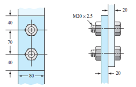
A bolted lap joint using ISO class 5.8 bolts and members made of cold-drawn SAE 1040 steel is shown in the figure. Assume the bolt threads do not extend into the joint. Find the tensile shear load F that can be applied to this connection to provide a minimum factor of safety of 2.5 for the following failure modes: shear of bolts, bearing on bolts, bearing on members, and tension of members.
Expert Solution & Answer
Want to see the full answer?
Check out a sample textbook solution
Students have asked these similar questions
The figure shows a connection that employs three SAE grade 4 bolts. The tensile shear load on the joint is
4000 lbf. The members are bars of AISI 1020 HR steel. Assume the bolt threads do not extend into the joint.
Find the factor of safety for each possible mode of failure. (Refer example problem 8.6 on pg. 445).
in ∞
in 100
in
1 in
in
Đ
1in
-2 in
in-20 UNC
5
5
in
in
The section of sealed joint shown in figure below is loaded by a force cycling between 2 and 6 kips.
The member have E = 30 Mpsi. The bolts have been preloaded to F; =35 kip each.
ž in-16 UNF x 24 in
SAE grade 5
No. 40 CI
(a) Find the fatigue factor of safety using Goodman criterion for above loading.
(b) Find the fatigue factor of safety using Goodman criterion if force cycling between 0 and 6 kips.
Required information
The bolted connection shown in the figure is subjected to a tensile shear load of 90 kN. The bolts are ISO class 5.8, and
the material is cold-drawn AISI 1015 steel. Assume the bolt threads do not extend into the joint. Find the factor of safety of
the connection for all possible modes of failure. Give the overall joint factor of safety. Given: t = 15 mm and t2 = 25 mm.
NOTE: This is a multi-part question. Once an answer is submitted, you will be unable to return to this part.
35
60
60
- 35
t1
M20 x 2.5
35
35
+ t2
Find the overall joint factor of safety.
The overall joint factor of safety noverall is
Chapter 8 Solutions
Shigley's Mechanical Engineering Design (McGraw-Hill Series in Mechanical Engineering)
Ch. 8 - A power screw is 25 mm in diameter and has a...Ch. 8 - Using the information in the footnote of Table...Ch. 8 - Show that for zero collar friction the efficiency...Ch. 8 - A single-threaded power screw is 25 mm in diameter...Ch. 8 - The machine shown in the figure can be used for a...Ch. 8 - The press shown for Prob. 8-5 has a rated load of...Ch. 8 - For the screw clamp shown, a force is applied at...Ch. 8 - The C clamp shown in the figure for Prob. 8-7 uses...Ch. 8 - Find the power required to drive a 1.5-in power...Ch. 8 - A single square-thread power screw has an input...
Ch. 8 - Prob. 11PCh. 8 - An M14 2 hex-head bolt with a nut is used to...Ch. 8 - Prob. 13PCh. 8 - A 2-in steel plate and a 1-in cast-iron plate are...Ch. 8 - Repeat Prob. 8-14 with the addition of one 12 N...Ch. 8 - A 2-in steel plate and a 1-in cast-iron plate are...Ch. 8 - Two identical aluminum plates are each 2 in thick,...Ch. 8 - Prob. 18PCh. 8 - A 30-mm thick AISI 1020 steel plate is sandwiched...Ch. 8 - Prob. 20PCh. 8 - Prob. 21PCh. 8 - Prob. 22PCh. 8 - A 2-in steel plate and a 1-in cast-iron plate are...Ch. 8 - An aluminum bracket with a 12-in thick flange is...Ch. 8 - An M14 2 hex-head bolt with a nut is used to...Ch. 8 - A 34 in-16 UNF series SAE grade 5 bolt has a 34-in...Ch. 8 - From your experience with Prob. 8-26, generalize...Ch. 8 - Prob. 28PCh. 8 - Prob. 29PCh. 8 - Prob. 30PCh. 8 - For a bolted assembly with eight bolts, the...Ch. 8 - Prob. 32PCh. 8 - 8-33 to 8-36 The figure illustrates the...Ch. 8 - 8-33 to 8-36 The figure illustrates the...Ch. 8 - 8-33 to 8-36 The figure illustrates the...Ch. 8 - 8-33 to 8-36 The figure illustrates the...Ch. 8 - Prob. 37PCh. 8 - Prob. 38PCh. 8 - 837 to 840 Repeat the requirements for the problem...Ch. 8 - Prob. 40PCh. 8 - 841 to 844 For the pressure vessel defined in the...Ch. 8 - Prob. 42PCh. 8 - Prob. 43PCh. 8 - Prob. 44PCh. 8 - Bolts distributed about a bolt circle are often...Ch. 8 - The figure shows a cast-iron bearing block that is...Ch. 8 - Prob. 47PCh. 8 - Prob. 48PCh. 8 - Prob. 49PCh. 8 - Prob. 50PCh. 8 - 851 to 854 For the pressure cylinder defined in...Ch. 8 - Prob. 52PCh. 8 - 851 to 854 For the pressure cylinder defined in...Ch. 8 - 851 to 854 For the pressure cylinder defined in...Ch. 8 - 855 to 858 For the pressure cylinder defined in...Ch. 8 - 855 to 858 For the pressure cylinder defined in...Ch. 8 - 855 to 858 For the pressure cylinder defined in...Ch. 8 - For the pressure cylinder defined in the problem...Ch. 8 - A 1-in-diameter hot-rolled AISI 1144 steel rod is...Ch. 8 - The section of the sealed joint shown in the...Ch. 8 - Prob. 61PCh. 8 - Prob. 62PCh. 8 - Prob. 63PCh. 8 - Prob. 64PCh. 8 - Using the Goodman fatigue criterion, repeat Prob....Ch. 8 - The figure shows a bolted lap joint that uses SAE...Ch. 8 - Prob. 67PCh. 8 - A bolted lap joint using ISO class 5.8 bolts and...Ch. 8 - Prob. 69PCh. 8 - The figure shows a connection that employs three...Ch. 8 - A beam is made up by bolting together two cold...Ch. 8 - Prob. 72PCh. 8 - Prob. 73PCh. 8 - Prob. 74PCh. 8 - A vertical channel 152 76 (see Table A7) has a...Ch. 8 - The cantilever bracket is bolted to a column with...Ch. 8 - Prob. 77PCh. 8 - The figure shows a welded fitting which has been...Ch. 8 - Prob. 79PCh. 8 - Prob. 80PCh. 8 - Prob. 81P
Knowledge Booster


Learn more about
Need a deep-dive on the concept behind this application? Look no further. Learn more about this topic, mechanical-engineering and related others by exploring similar questions and additional content below.Similar questions
- (11) The figure shows a connection that employs three SAE grade 5 bolts. The tensile shear load on the joint is 5400 lbf. The members are cold-drawn bars of AISI 1020 steel. Find the factor of safety for each possible mode of failure. (Ans./ 3.26, 5.99, 3.71, 5.36) in- 글im 16 UNC in I in -24 in-arrow_forwardTwo plates are clamped by a 3/4-10 UNC SAE Grade 5 bolt and regular nut with a 3/4-W plain washer as shown in figure. Top plate is made of grey cast iron and bottom plate is steel. An axial force of 12kN is acted upon the joint. Round off the length of the bolt to nearest 1/4in. Assume bolts are preloaded to 75% of proof load. 1. Determine the bolt stiffness kb. 2. Determine the member stiffness km. 3. Determine the yielding factor of safety of the bolt. 4. Determine the load factor for the bolt. 5. Determine the load factor guarding against joint separation. 1.25 in 1.00 inarrow_forward8-68 Engineering Design + 40 1 plem 8-68 70 millimeters. 40 A bolted lap joint using ISO class 5.8 bolts and members made of cold-drawn SAE 1040 steel is shown in the figure. Assume the bolt threads do not extend into the joint. Find the tensile shear load F that can be applied to this connection to provide a minimum factor of safety of 2.5 for the fol- lowing failure modes: shear of bolts, bearing on bolts, bearing on members, and tension of members. 20 M20x2.5 20arrow_forward
- (8) The bolted connection shown in the figure uses SAE grade 5 bolts. The members are hot-rolled AISI 1018 steel. A tensile shear load F = 4000 lbf is applied to the connection. Find the factor of safety for all possible modes of failure. (Ans/2.93, 4.32, 1.5, 3.25) in in-16 UNC ț in inarrow_forwardA bolted lap joint using ISO class 5.8 bolts and members made of cold-drawn SAE 1040 steel is shown in the figure. Find the tensile shear load F that can be applied to this connection to provide a minimum factor of safety of 2.5 for the following failure modes: shear of bolts, bearing on bolts, bearing on members, and tension of members. 40 70 M20x2.5 20arrow_forwardA bolted lap joint using ISO 5.8 bolts and members made from cold-drawn SAE 1040 steel is shown in the figure. Assume the bolt threads do not extend into the joint. Find the tensile shear load F that can be applied to this connection to provide a minimum factor of safety of 2.5 for the following failure modes: shear of bolts, bearing on bolts, bearing on members, and tension of members. 40 ↑ 70 40 ↑ 80 M20 × 2.5 20 20arrow_forward
- As shown in figure below, two plates are clamped by washer-faced 2 in-20 UNF SAE grade 5 bolts each with a standard 2 N steel plain washer. The top plate is steel and the bottom pplate is gray cast iron. If a total of 8 bolts where used to close 1 feet diameter pipe which applied at maximum pressure of 150 psi. Calculate the static and fatigue safety factor of this joint. Used Goodman theory for tha fatigue safety 1/2 factor. 3/4arrow_forward4. Determine the design stress for bolts in a cylinder cover where the load is fluctuating due to gas pressure. The maximum load on the bolt is 50 kN and the minimum is 30 kN. The load is unpredict- able and factor of safety is 3. The surface of the bolt is hot rolled and the suface finish factor is 0.9. During a simple tension test and rotating beam test on ductile materials (40 C 8 steel annealed), the following results were obtained : Diameter of specimen =12.5 mm; Yield strength= 240 MPa; Ultimate strength= 450 MPa; Endurance limit = 180 MPa. [Ans. 65.4 MPa]arrow_forwardThe figure gives the cross-section of a grade 25 cast-iron pressure vessel. A total of N bolts are to be used to resist a separating force of 150 kN. (a) Determine kb, km, and C. (b) Find the number of bolts required for a load factor of 2 where the bolts may be reused when the joint is taken apart. (c) With the number of bolts obtained in part (b), determine the realized load factor for overload, the yielding factor of safety, and the load factor for joint separation. Use (SI) units as it appliesarrow_forward
- A vertical channel 152 x 76 (see Table A-7) has a cantilever beam bolted to it as shown. The channel is hot-rolled AISI 1006 steel. The bar is of hot-rolled AISI 1015 steel. The shoulder bolts are M10 x 1.5 ISO 5.8. Assume the bolt threads do not extend into the joint. For a design factor of 2.2, find the safe force Fthat can be applied to the cantilever. 12 50 +50--50-- 26! 125 The maximum allowable force on the system Fis N.arrow_forwardData: r=0.25 inch, d=0.4 pig and h=0.5 inch, wi=2.5 inch and w= 1.5 inch.The forces fluctuate between a tension of 14 Kips and a compression of 5 Kips. It is made of AISI 1018 CD. steel.The connecting element in the figure is failing. What is the most critical point and give recommendations to improve the situation.arrow_forwardFigure Q1 shows a structure under a concentrated force of P. Pins A, B, E, and F are single-shear with a 21-mm diameter. The connections at D is double shear connection with a 21-mm diameter. All pins are made of Aluminum 2014-T6. Based on yield stress, minimum factor of safety is 1.5 for all parts of below structure. Determine maximum concentrated force P, that can apply on the structure. (The cross sectional area of members EA and FB are 330 mm² and 250 mm² respectively). 350 mm 600 mm 900 mm E Copper Brass C83400 F Copper Bronze C86100 Figure Q1 A B 720 mm P Darrow_forward
arrow_back_ios
SEE MORE QUESTIONS
arrow_forward_ios
Recommended textbooks for you
 Mechanics of Materials (MindTap Course List)Mechanical EngineeringISBN:9781337093347Author:Barry J. Goodno, James M. GerePublisher:Cengage Learning
Mechanics of Materials (MindTap Course List)
Mechanical Engineering
ISBN:9781337093347
Author:Barry J. Goodno, James M. Gere
Publisher:Cengage Learning
EVERYTHING on Axial Loading Normal Stress in 10 MINUTES - Mechanics of Materials; Author: Less Boring Lectures;https://www.youtube.com/watch?v=jQ-fNqZWrNg;License: Standard YouTube License, CC-BY