
Shigley's Mechanical Engineering Design (McGraw-Hill Series in Mechanical Engineering)
10th Edition
ISBN: 9780073398204
Author: Richard G Budynas, Keith J Nisbett
Publisher: McGraw-Hill Education
expand_more
expand_more
format_list_bulleted
Concept explainers
Videos
Textbook Question
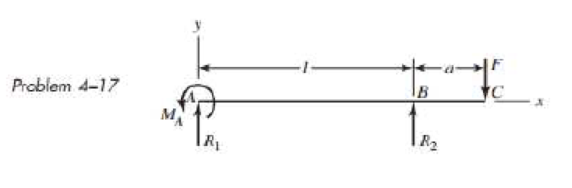
Chapter 4, Problem 17P
A simply supported beam has a concentrated moment MA applied at the left support and a concentrated force F applied at the free end of the overhang on the right. Using superposition, determine the deflection equations in regions AB and BC.
Expert Solution & Answer
Want to see the full answer?
Check out a sample textbook solution
Students have asked these similar questions
Home Work:
1. Determine the maximum deflection d in a simply supported beam of length L
carrying a uniformly distributed load of intensity w, applied over its entire length.
2. For the beam loaded as shown in the Figure, compute the moment of area of the
M diagrams between the reactions about both the left and the right reaction. (Hint:
Draw the moment diagram by parts from right to left).
500 N
2 m
1 m
1 m
400 N/m
B
R1
R2
Please solve according to
the exporters of a typical
solution.
1
M
E*I
3. Moment Diagram by Parts
but
ds = pd0
M
de
M
ds
E*I
1
The construction of moment diagram by parts depends on two basic principles:
1) The resultant bending moment at any section caused by any load system is the
algebraic sum of the bending moment at that section caused by each load acting
separately.
= de =
%3D
E*I
ds
but
ds = dx
(Flat curve)
M
Σ
. de =
-) M. =
MR
M =
E * I
1
(M * dx
EML,EMR : Sum of the moment caused by all the forces to the left and right
section respectively.
.. 0 =
E * I
2)…
3. Two beams are supported as shown in the diagram below, each 150mm x 200mm x 6 meters. Beam CD is a
cantilever beam carrying a uniformly distributed load of 6 KN/m freely supported on beam AB. Beam AB is
freely supported on each ends. E = 13.8 GPa for both beam. Neglect the weight of the beam.
a. Compute the reaction at D.
b. Compute the deflection at D.
c. Compute the bending stress of beam CD.
6 ka lm
бт
6m
6m
Calculate the support reaction at A and B for the beam shown in the figure below.
Take F= 570 N.
F
A
B
3M
1M
Ay
By
Reaction force at point B
By=
N.
Reaction force at point A
Ay
N.
Chapter 4 Solutions
Shigley's Mechanical Engineering Design (McGraw-Hill Series in Mechanical Engineering)
Ch. 4 - The figure shows a torsion bar OA fixed at O,...Ch. 4 - For Prob. 41, if the simple support at point A...Ch. 4 - A torsion-bar spring consists of a prismatic bar,...Ch. 4 - An engineer is forced by geometric considerations...Ch. 4 - A bar in tension has a circular cross section and...Ch. 4 - Prob. 6PCh. 4 - Prob. 7PCh. 4 - Derive the equations given for beam 2 in Table A9...Ch. 4 - Derive the equations given for beam 5 in Table A9...Ch. 4 - The figure shows a cantilever consisting of steel...
Ch. 4 - A simply supported beam loaded by two forces is...Ch. 4 - Using superposition, find the deflection of the...Ch. 4 - A rectangular steel bar supports the two...Ch. 4 - An aluminum tube with outside diameter of 2 in and...Ch. 4 - The cantilever shown in the figure consists of two...Ch. 4 - Using superposition for the bar shown, determine...Ch. 4 - A simply supported beam has a concentrated moment...Ch. 4 - Prob. 18PCh. 4 - Using the results of Prob. 418, use superposition...Ch. 4 - Prob. 20PCh. 4 - Consider the uniformly loaded simply supported...Ch. 4 - Prob. 22PCh. 4 - Prob. 23PCh. 4 - Prob. 24PCh. 4 - Prob. 25PCh. 4 - Prob. 26PCh. 4 - Prob. 27PCh. 4 - Prob. 28PCh. 4 - 429 to 434 For the steel countershaft specified in...Ch. 4 - Prob. 30PCh. 4 - Prob. 31PCh. 4 - Prob. 32PCh. 4 - For the steel countershaft specified in the table,...Ch. 4 - For the steel countershaft specified in the table,...Ch. 4 - Prob. 35PCh. 4 - Prob. 36PCh. 4 - Prob. 37PCh. 4 - Prob. 38PCh. 4 - Prob. 39PCh. 4 - Prob. 40PCh. 4 - The cantilevered handle in the figure is made from...Ch. 4 - Prob. 42PCh. 4 - The cantilevered handle in Prob. 384, p. 154, is...Ch. 4 - A flat-bed trailer is to be designed with a...Ch. 4 - The designer of a shaft usually has a slope...Ch. 4 - Prob. 46PCh. 4 - If the diameter of the steel beam shown is 1.25...Ch. 4 - For the beam of Prob. 4-47, plot the magnitude of...Ch. 4 - Prob. 49PCh. 4 - 4-50 and 4-51 The figure shows a rectangular...Ch. 4 - and 451 the ground at one end and supported by a...Ch. 4 - The figure illustrates a stepped torsion-bar...Ch. 4 - Consider the simply supported beam 5 with a center...Ch. 4 - Prob. 54PCh. 4 - Prob. 55PCh. 4 - Solve Prob. 410 using singularity functions. Use...Ch. 4 - Prob. 57PCh. 4 - Prob. 58PCh. 4 - Prob. 59PCh. 4 - Solve Prob. 413 using singularity functions. Since...Ch. 4 - Prob. 61PCh. 4 - Solve Prob. 419 using singularity functions to...Ch. 4 - Using singularity functions, write the deflection...Ch. 4 - Determine the deflection equation for the...Ch. 4 - Use Castiglianos theorem to verify the maximum...Ch. 4 - Use Castiglianos theorem to verify the maximum...Ch. 4 - Solve Prob. 415 using Castiglianos theorem.Ch. 4 - Solve Prob. 452 using Castiglianos theoremCh. 4 - Determine the deflection at midspan for the beam...Ch. 4 - Using Castiglianos theorem, determine the...Ch. 4 - Solve Prob. 441 using Castiglianos theorem. Since...Ch. 4 - Solve Prob. 442 using Castiglianos theorem.Ch. 4 - The cantilevered handle in Prob. 384 is made from...Ch. 4 - Solve Prob. 450 using Castiglianos theorem.Ch. 4 - Solve Prob. 451 using Castiglianos theorem.Ch. 4 - The steel curved bar shown has a rectangular cross...Ch. 4 - Repeat Prob. 476 to find the vertical deflection...Ch. 4 - For the curved steel beam shown. F = 6.7 kips....Ch. 4 - A steel piston ring has a mean diameter of 70 mm....Ch. 4 - For the steel wire form shown, use Castiglianos...Ch. 4 - 4-81 and 4-82 The part shown is formed from a...Ch. 4 - 4-81 and 4-82 The part shown is formed from a...Ch. 4 - Repeat Prob. 481 for the vertical deflection at...Ch. 4 - Repeat Prob. 482 for the vertical deflection at...Ch. 4 - A hook is formed from a 2-mm-diameter steel wire...Ch. 4 - The figure shows a rectangular member OB, made...Ch. 4 - Prob. 87PCh. 4 - For the wire form shown, determine the deflection...Ch. 4 - Prob. 89PCh. 4 - Prob. 90PCh. 4 - Prob. 91PCh. 4 - Prob. 92PCh. 4 - Solve Prob. 492 using Castiglianos method and...Ch. 4 - An aluminum step bar is loaded as shown. (a)...Ch. 4 - The steel shaft shown in the figure is subjected...Ch. 4 - Repeat Prob. 495 with the diameters of section OA...Ch. 4 - The figure shows a 12- by 1-in rectangular steel...Ch. 4 - For the beam shown, determine the support...Ch. 4 - Solve Prob. 498 using Castiglianos theorem and...Ch. 4 - Consider beam 13 in Table A9, but with flexible...Ch. 4 - Prob. 101PCh. 4 - The steel beam ABCD shown is simply supported at C...Ch. 4 - Prob. 103PCh. 4 - A round tubular column has outside and inside...Ch. 4 - For the conditions of Prob. 4104, show that...Ch. 4 - Link 2, shown in the figure, is 25 mm wide, has...Ch. 4 - Link 3, shown schematically in the figure, acts as...Ch. 4 - The hydraulic cylinder shown in the figure has a...Ch. 4 - The figure shows a schematic drawing of a...Ch. 4 - If drawn, a figure for this problem would resemble...Ch. 4 - Design link CD of the hand-operated toggle press...Ch. 4 - Find the maximum values of the spring force and...Ch. 4 - As shown in the figure, the weight W1 strikes W2...Ch. 4 - Part a of the figure shows a weight W mounted...
Knowledge Booster


Learn more about
Need a deep-dive on the concept behind this application? Look no further. Learn more about this topic, mechanical-engineering and related others by exploring similar questions and additional content below.Similar questions
- Use the method of superposition to find the angles of rotation 9Aand SBat the supports, and the maximum deflection for a simply supported beam subjected to symmetric loads P at distance a from each support. Assume that EI is constant, total beam length is L and a = U3. Hint: Use the formulas of Example 9-3.arrow_forwardHome Work: 1. Determine the maximum deflection d in a simply supported beam of length L carrying a uniformly distributed load of intensity w, applied over its entire length. 2. For the beam loaded as shown in the Figure, compute the moment of area of the M diagrams between the reactions about both the left and the right reaction. (Hint: Draw the moment diagram by parts from right to left). 500 N 2 m 1 m 1 m 400 N/m R1 R2 Please solve according to the exporters of a typical solution. 1 E*I 3. Moment Diagram by Parts but ds = pd0 M de M ds E*I 1 The construction of moment diagram by parts depends on two basic principles: 1) The resultant bending moment at any section caused by any load system is the = de = %3D E*I ds algebraic sum of the bending moment at that section caused by each load acting separately. but ds = dx (Flat curve) M =) M2 = Σ = OP ** E * I MR 1 [M * dx EM,EMR : Sum of the moment caused by all the forces to the left and right section respectively. :. 0 = E * I 2) The…arrow_forwardGiven the simple beam as shown below. Determine the following: 100 N/m 30 N/m A 2 m B 7m mum. 2m D The External Reaction at Point B. The External Reaction at Point C.arrow_forward
- 4. Determine the expression for the deflection at the tip (Point B) in the direction of the applied Force F for the following handle. Use Energy Methods.arrow_forwardSample Problem: Determine the reactions for the beam loaded as shown in the figure 15 KN/m below. 12 KN 6 KN /m 3m Rz R. 1.5 marrow_forwardFind the torsion constant of the following beam cross section.arrow_forward
- Find the bending moment at point B and draw the constant-force and bending-moment diagrams for the beam shown in the figure. Include the free-body diagram and the correct units.arrow_forwardFigure 1 shows a cantilever beam which is 6 m long and fixed at A. The beam carries a uniformly distributed load of 30 kN/m over its full length. A moment of 50 kNm is applied at 3 m from the fixed support, at B. Determine the slope and deflection at points B and C using the conjugate beam method (E = 200 GPa and I = 1500 × 106 mm*). 50 kNm 30 kN/m B 3 m 3 m 51 Iarrow_forwardfind the reactions for the beam shown! Draw Shear + moment diagram. Use superposition method!arrow_forward
- determine the equation for the elastic curve of a beam that is subjected to an applied oment and distributed load and to use this equation to determine the deflection of the eam at given locations along the beam's length. Part A - Moment reaction at point A e cantilever beam shown below has an applied moment of M = 28.0 kip - in at point B ad a distributed load of wo = 6.0 kip/in centered at point C. The beam is fixed to a wall at int A, has a modulus of elasticity of E = 28000 ksi , and a moment of inertia of I = 55.0 4 Assume El is constant. The measurements corresponding b = 10.5 in , c = 11.0 in , and d = 5.5 in (Figure 1) The first step in analyzing this problem is to detemine the reactions on the beam at the wall (point A). Assuming a counterclockwise value to be positive, what is the moment reaction a Express your answer to three significant figures and include appropriate units. the figure are a = 11.5 • View Available Hint(s) ? M = Value Units Submit Part B - Elastic curve for…arrow_forwardA beam with a uniform load has a sliding support at one end and spring support at the other. The spring has a stiffness k = 48EI / L3. Derive the equation of the deflection curve by starting with the third-order differential equation (the shear-force equation). Also, determine the angle of rotation θB at support B.arrow_forwardSHOW THE FOLLOWING: 1. COMPUTATION OF REACTIONS 2. SHEAR AND MOMENT DIAGRAM 3. MAXIMUM BENDING MOMENT @ THE LOACTION OF THE MAXIMUM DEFLECTION 4. VALUE OF THE MAXIMUM DEFLECTION (A/B). A beam 7 m long is simply supported at its ends and loaded as follows: 120 kN at 1 m from one end A, 20kN at 4 m from A and 60 kN at 5 m from A. Calculate the position and magnitude of the maximum deflection. The second moment of area of the beam section is 400 x 10-m* and E for the beam material is 210 GN/m².arrow_forward
arrow_back_ios
SEE MORE QUESTIONS
arrow_forward_ios
Recommended textbooks for you
 Mechanics of Materials (MindTap Course List)Mechanical EngineeringISBN:9781337093347Author:Barry J. Goodno, James M. GerePublisher:Cengage Learning
Mechanics of Materials (MindTap Course List)
Mechanical Engineering
ISBN:9781337093347
Author:Barry J. Goodno, James M. Gere
Publisher:Cengage Learning
Solids: Lesson 53 - Slope and Deflection of Beams Intro; Author: Jeff Hanson;https://www.youtube.com/watch?v=I7lTq68JRmY;License: Standard YouTube License, CC-BY