
Videos
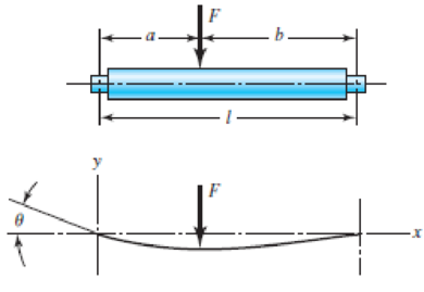
The designer of a shaft usually has a slope constraint imposed by the bearings used. This limit will be denoted as ξ. If the shaft shown in the figure is to have a uniform diameter d except in the locality of the bearing mounting, it can be approximated as a uniform beam with simple supports. Show that the minimum diameters to meet the slope constraints at the left and right bearings are, respectively,
Problem 4–45
Want to see the full answer?
Check out a sample textbook solution
Chapter 4 Solutions
Shigley's Mechanical Engineering Design (McGraw-Hill Series in Mechanical Engineering)


- A horizontal bracket ABC consists of two perpendicular arms AB of a length 0.75 m and BC of a length 0.5 m. The bracket has a solid, circularcross section with a diameter equal to 65 mm. The bracket is inserted in a frictionless sleeve at A (which is slightly larger in diameter), so it is free to rotate about the z0 axis at A and is supported by a pin at C.Moments are applied at point C M1 = 1.5 kN m in the x direction and M2 = 1.0 kN. m acts in the -z direction.Considering only the moments M1 and M2, calculate the maximum tensile stress σv, the maximum compressive stress σc, and the maximum in-planeshear stress τmax at point p, which is located at support port A on the side of the bracket at mid-height.arrow_forwardThe 46-mm diameter shaft is supported by a smooth thrust bearing at A and a smooth journal bearing at B. The pulleys C and D are subjected to the vertical and horizontal loadings shown in the figure below. (Figure 1) Figure 400 mm 400 mm C C 300 N 300 N 400 mm D < 150 N 150 N B 1 of 1 ▶ Part A Determine the absolute maximum bending stress in the shaft. Express your answer to three significant figures and include the appropriate units. Omax= Submit Provide Feedback uA Value f Request Answer t O Units ?arrow_forwardASAParrow_forward
- * For the cross section shown in the figure. Given the value of Y= 172 mm. Find the :value of total moment of Inertia 250 mm A1 Neutral Axis (N.A) A2 Ý Reference Line 50 mm 40 mm 220 mm 145.2 x 10^6 mm^4 119.7 x 10^6 mm^4 169.4 x 10^6 mm^4 129.5 x 10^6 mm^4 O 119.7 x 10^6 mm^3 O 119.7 x 10^6 mm^2 119.7 x 10^6 mm 134.2 x 10^6 mm^4 O 47.57 x 10^6 mm^4 O 193.1 x 10^6 mm^4 86.65 x 10^6 mm^4arrow_forwardThe figure below shows the cross-section of an axisymmetric composite beam that comprises steel (Young's modulus 270 GPa) and aluminum (Young's modulus 90 GPa) sections that are bonded together. The steel section is of wall thickness 15 mm and the aluminum section is of wall thickness 10mm. The steel section comprises 4 axisymmetric holes of 5 mm diameter as shown. Given that the beam is bent by a couple moment of 1200 Nm, determine the maximum stress in steel and aluminum. 4 holes of diameter 5 mm. 12 mm steel aluminumarrow_forward6. Compute the maximum shear stress and the statical moment for a steel rod with a diameter of 10 in, with a maximum moment of 520 lb ft and a maximum shear of 12 kips (see image below to see information regarding centroids). Data: D = 10 in M = 520 lb-ft V = 12 kips Solution: 1= Ap πT Dª = 64 1 = 490.87 in¹ · (H-DP-²) = Tmax= 2D y === 2.12 in 3m Q=A, y = 83.33 in³ = 39.27 in² V.Q 1 t = 203.72 psi Circular Ap. y= 2D 3marrow_forward
- The rigid beam shown in is held by two vertical rods at A and C.If a 60 KN load is applied at B what is the displacement of this point (B) . Aluminum L- 3m A- 500 mm E- 70 GPa Steel L- 4 m A= 300 mm E- 200 GPa 3.5 m 2.5 marrow_forwardThe shaft is supported by a smooth thrust bearing at A and a smooth journal bearing at B. Take: d1 = 1 m, d2 =1 m, d3 = 1 m, d4 = 1.2 m, d5 = 1.4 m, F1 = 691 N/m, and F2 = 1,189 N. Determine the bending moment (Mc) acting on the cross section at C in N-m. Hint: consider the sign convention for internal loods. F1 В + di d2 d3 d4 ds F2arrow_forwardThe beam is supported by double-shear pins at A, B, and C. The radius of all the pins are r = 8 mm. Hint: 1. Remember that rod BC is a 2-force member 0₁ Variable F₁ F2 F3 F₁ d₁ d₂ 0₁ d₁ NBC OB = F₁ d2 Value F₂ 12 KN 38 KN 60 KN 28 KN 0.75 m 1.25 m 30 degrees Values for the figure are given in the following table. Note the figure may not be to scale. d2 F₁ dz KN F₁ a. Determine the magnitude of the normal force in rod BC, NBC. b. Determine the magnitude of the reaction force in pin A, A c. Determine the average shear stress in pin A, TA. d. Determine the average shear stress in pin B, TB. e. Determine the average shear stress in pin C, TC. d₁ Round your final answers to 3 significant digits/figures.arrow_forward
- 1. A simply supported beam with length of 5 Meters is loaded with a counterclockwise couple of 5 KN.M at I Meter from the left support and a point load of 5 KN at 3 Meters from the left support. The beam is an I-Section with the following dimensions: bf = 250 MM tf = 16 MM tw = 10MM d = 350 MM Determine the MaxiMUM tensile and compressive bending stress developed in the beam. 2. A simply supported beam with a length of 4M is loaded with a uniform distributed load (w). The beam has a rectangular hollow section with the following dimensions: Outer Base = 150 MM Outer Depth = 200 MM Inner Base = 100 MM Inner Depth = 150 mm Determine the maximum uniformly distributed load which can be applied over the entire length of the beam if the bending stress is limited to 8 Mpa.arrow_forwardThe figure shown is an I-beam weighing 10 kips/ft which is supported by two columns. If the support at B is roller and C is pinned. Determine the maximum moment of the beam. 10 kips/ft A B A) 0.289 kips-ft (B) 0.268 kips-ft 0.293 kips-ft D 2.81 kips-ft E None of the choices are correct 0.75 ft 1 ftarrow_forwardSmooth journal bearings at A and B that only exert vertical reactions on the shaft as shown below support the shaft. Based on the loading and support conditions shown, address the following: (a) Sketch the shear and moment diagrams using the graphical method - label all significant conditions. (b) If d = 90 mm, determine the absolute maximum bending stress in the beam, and sketch the stress distribution acting over the cross section. A 3 m 12 kN/m B 1.5 marrow_forward
 Elements Of ElectromagneticsMechanical EngineeringISBN:9780190698614Author:Sadiku, Matthew N. O.Publisher:Oxford University Press
 Mechanics of Materials (10th Edition)Mechanical EngineeringISBN:9780134319650Author:Russell C. HibbelerPublisher:PEARSON
 Thermodynamics: An Engineering ApproachMechanical EngineeringISBN:9781259822674Author:Yunus A. Cengel Dr., Michael A. BolesPublisher:McGraw-Hill Education
 Control Systems EngineeringMechanical EngineeringISBN:9781118170519Author:Norman S. NisePublisher:WILEY
 Mechanics of Materials (MindTap Course List)Mechanical EngineeringISBN:9781337093347Author:Barry J. Goodno, James M. GerePublisher:Cengage Learning
 Engineering Mechanics: StaticsMechanical EngineeringISBN:9781118807330Author:James L. Meriam, L. G. Kraige, J. N. BoltonPublisher:WILEY