
Shigley's Mechanical Engineering Design (McGraw-Hill Series in Mechanical Engineering)
10th Edition
ISBN: 9780073398204
Author: Richard G Budynas, Keith J Nisbett
Publisher: McGraw-Hill Education
expand_more
expand_more
format_list_bulleted
Videos
Textbook Question
thumb_up100%
Chapter 4, Problem 94P
An aluminum step bar is loaded as shown. (a) Verify that end C deflects to the rigid wall, and (b) determine the wall reaction forces, the stresses in each member, and the deflection of B.
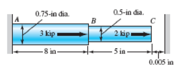
Problem 4–94
(Not drawn to scale)
Expert Solution & Answer
Want to see the full answer?
Check out a sample textbook solution
Students have asked these similar questions
All members shown in the figure are made of Aluminum 2024 with the Young's Modulus of 10.6(106) psi
and has a diameter of 4 in. Find all the reactions and loads in all members of the truss structure and the axial
deformations in the vertical components. (Use Method of Joints and include all Free-Body Diagram per joint;
indicate compression or tension)
B
10 ft
KB
5 ft
500 lbs
10 ft
A diagonal aluminum alloy tension rod of diameter d and initial length I is used in a rectangular
frame to prevent collapse. The rod can safely support a tensile stress of oallow. If d = 0.5 in, / = 8
ft, and oallow = 20 kpsi, determine how much the rod must be stretched to develop this allowable
stress.
The factor of safety for a machine element depends on the particular point selected for analysis. For the bar and loading, shown in the figure below, we need to have a minimum factor of safety, ηy = 2.5. The bar is to be made of AISI 1050 cold-drawn steel and is loaded by F = 2.65 kN, P = 10.5 kN, and T = 52 N-m.
Draw planar stress elements (A and B) showing normal and shear stresses at their proper orientations.
Determine a safe diameter d to the nearest mm, based upon the distortion-energy theory, for both stress elements at A and B of the member shown in the figure.
Determine the safe diameter, d, based on maximum shear stress theory.
You are the designer, and you are to decide on the safe diameter, chosen from one of the diameters obtained from different failure theories used in parts (b) and (c) above, and explain your final decision made on the diameter.
Chapter 4 Solutions
Shigley's Mechanical Engineering Design (McGraw-Hill Series in Mechanical Engineering)
Ch. 4 - The figure shows a torsion bar OA fixed at O,...Ch. 4 - For Prob. 41, if the simple support at point A...Ch. 4 - A torsion-bar spring consists of a prismatic bar,...Ch. 4 - An engineer is forced by geometric considerations...Ch. 4 - A bar in tension has a circular cross section and...Ch. 4 - Prob. 6PCh. 4 - Prob. 7PCh. 4 - Derive the equations given for beam 2 in Table A9...Ch. 4 - Derive the equations given for beam 5 in Table A9...Ch. 4 - The figure shows a cantilever consisting of steel...
Ch. 4 - A simply supported beam loaded by two forces is...Ch. 4 - Using superposition, find the deflection of the...Ch. 4 - A rectangular steel bar supports the two...Ch. 4 - An aluminum tube with outside diameter of 2 in and...Ch. 4 - The cantilever shown in the figure consists of two...Ch. 4 - Using superposition for the bar shown, determine...Ch. 4 - A simply supported beam has a concentrated moment...Ch. 4 - Prob. 18PCh. 4 - Using the results of Prob. 418, use superposition...Ch. 4 - Prob. 20PCh. 4 - Consider the uniformly loaded simply supported...Ch. 4 - Prob. 22PCh. 4 - Prob. 23PCh. 4 - Prob. 24PCh. 4 - Prob. 25PCh. 4 - Prob. 26PCh. 4 - Prob. 27PCh. 4 - Prob. 28PCh. 4 - 429 to 434 For the steel countershaft specified in...Ch. 4 - Prob. 30PCh. 4 - Prob. 31PCh. 4 - Prob. 32PCh. 4 - For the steel countershaft specified in the table,...Ch. 4 - For the steel countershaft specified in the table,...Ch. 4 - Prob. 35PCh. 4 - Prob. 36PCh. 4 - Prob. 37PCh. 4 - Prob. 38PCh. 4 - Prob. 39PCh. 4 - Prob. 40PCh. 4 - The cantilevered handle in the figure is made from...Ch. 4 - Prob. 42PCh. 4 - The cantilevered handle in Prob. 384, p. 154, is...Ch. 4 - A flat-bed trailer is to be designed with a...Ch. 4 - The designer of a shaft usually has a slope...Ch. 4 - Prob. 46PCh. 4 - If the diameter of the steel beam shown is 1.25...Ch. 4 - For the beam of Prob. 4-47, plot the magnitude of...Ch. 4 - Prob. 49PCh. 4 - 4-50 and 4-51 The figure shows a rectangular...Ch. 4 - and 451 the ground at one end and supported by a...Ch. 4 - The figure illustrates a stepped torsion-bar...Ch. 4 - Consider the simply supported beam 5 with a center...Ch. 4 - Prob. 54PCh. 4 - Prob. 55PCh. 4 - Solve Prob. 410 using singularity functions. Use...Ch. 4 - Prob. 57PCh. 4 - Prob. 58PCh. 4 - Prob. 59PCh. 4 - Solve Prob. 413 using singularity functions. Since...Ch. 4 - Prob. 61PCh. 4 - Solve Prob. 419 using singularity functions to...Ch. 4 - Using singularity functions, write the deflection...Ch. 4 - Determine the deflection equation for the...Ch. 4 - Use Castiglianos theorem to verify the maximum...Ch. 4 - Use Castiglianos theorem to verify the maximum...Ch. 4 - Solve Prob. 415 using Castiglianos theorem.Ch. 4 - Solve Prob. 452 using Castiglianos theoremCh. 4 - Determine the deflection at midspan for the beam...Ch. 4 - Using Castiglianos theorem, determine the...Ch. 4 - Solve Prob. 441 using Castiglianos theorem. Since...Ch. 4 - Solve Prob. 442 using Castiglianos theorem.Ch. 4 - The cantilevered handle in Prob. 384 is made from...Ch. 4 - Solve Prob. 450 using Castiglianos theorem.Ch. 4 - Solve Prob. 451 using Castiglianos theorem.Ch. 4 - The steel curved bar shown has a rectangular cross...Ch. 4 - Repeat Prob. 476 to find the vertical deflection...Ch. 4 - For the curved steel beam shown. F = 6.7 kips....Ch. 4 - A steel piston ring has a mean diameter of 70 mm....Ch. 4 - For the steel wire form shown, use Castiglianos...Ch. 4 - 4-81 and 4-82 The part shown is formed from a...Ch. 4 - 4-81 and 4-82 The part shown is formed from a...Ch. 4 - Repeat Prob. 481 for the vertical deflection at...Ch. 4 - Repeat Prob. 482 for the vertical deflection at...Ch. 4 - A hook is formed from a 2-mm-diameter steel wire...Ch. 4 - The figure shows a rectangular member OB, made...Ch. 4 - Prob. 87PCh. 4 - For the wire form shown, determine the deflection...Ch. 4 - Prob. 89PCh. 4 - Prob. 90PCh. 4 - Prob. 91PCh. 4 - Prob. 92PCh. 4 - Solve Prob. 492 using Castiglianos method and...Ch. 4 - An aluminum step bar is loaded as shown. (a)...Ch. 4 - The steel shaft shown in the figure is subjected...Ch. 4 - Repeat Prob. 495 with the diameters of section OA...Ch. 4 - The figure shows a 12- by 1-in rectangular steel...Ch. 4 - For the beam shown, determine the support...Ch. 4 - Solve Prob. 498 using Castiglianos theorem and...Ch. 4 - Consider beam 13 in Table A9, but with flexible...Ch. 4 - Prob. 101PCh. 4 - The steel beam ABCD shown is simply supported at C...Ch. 4 - Prob. 103PCh. 4 - A round tubular column has outside and inside...Ch. 4 - For the conditions of Prob. 4104, show that...Ch. 4 - Link 2, shown in the figure, is 25 mm wide, has...Ch. 4 - Link 3, shown schematically in the figure, acts as...Ch. 4 - The hydraulic cylinder shown in the figure has a...Ch. 4 - The figure shows a schematic drawing of a...Ch. 4 - If drawn, a figure for this problem would resemble...Ch. 4 - Design link CD of the hand-operated toggle press...Ch. 4 - Find the maximum values of the spring force and...Ch. 4 - As shown in the figure, the weight W1 strikes W2...Ch. 4 - Part a of the figure shows a weight W mounted...
Knowledge Booster


Learn more about
Need a deep-dive on the concept behind this application? Look no further. Learn more about this topic, mechanical-engineering and related others by exploring similar questions and additional content below.Similar questions
- A steel pad supporting heavy machinery rests on four short, hollow, cast iron piers (see figure). The ultimate strength of the cast iron in compression is 400 MPa. The total load P that may be supported by the pad is 900 kN. Using a factor or safely 3.0 with respect to ultimate strength, determine the outer diameter of the pier if the thickness, is of the cross section is 12 mm.arrow_forward(4) The plunger of an oil pump is held against the operating cam by a spring made of No.10 W&M gage steel wire coiled with an outside diameter of 7%-in. There are five active coils. The open length is 1.1875in. What are the length & stress when a load of 30lb is applied.arrow_forwardThe composite bar, firmly attached to unyielding supports, is initially stress-free. What maximum axial load P can be applied if the allowable stresses are 10 ksi for aluminum and 18 ksi for steel?arrow_forward
- 1. Use the tabulated solutions: Calculate the critical buckling stress for each of the flat plates shown. All are made from steel with E = 29 X 106 psi and v = 0.30 and are 3/16 inch thick. All edges are simply supported. (a) 48 in 48 in ' (b) 96 in 48 in (c) 48 in Note: if the tabulated solutions do not include the exact geometry ratio that you are looking for, interpolate between values in the table. 96 inarrow_forward3. The 10-ft wooden column has the rectangular cross-section with dimension shown in the diagram. Take the elasticity E = 1.6 Msi, and yielding strength in compression oy = -5 ksi. a) Determine the critical load if the bottom is fixed and the top is pinned. b) If this critical load is acting on the column, calculate the normal stress. Is the wood yielded? c) Calculate the radius of gyration of the column. d) Determine the critical load if the bottom and top are both fixed. 10 ft 4 in. 2 in.arrow_forwardHomework 3 m 13: Find the stresses in members BC, BD, and CF for the truss 3 m C 4 m hown in Fig. Indicate the tension or compression. The cross ectional area of each member is 1600 mm'. 60 kN 90 kN 4 m Figure P-113arrow_forward
- 3. A tensile force is applied to the I-shaped piece of wood in a testing machine, in the arrangement shown. The dimensions are b = 26 mm, t 12 mm, w = 34 mm, and the thickness (into the page) = 14 mm. (The wood has a rectangular cross section.) The wood has a failure normal stress (ofail) of 1.2 MPa, a failure she ar stress (Tfait) of 18 MPa, and a failure bearing stress (Orail.bra) of 0.9 M Pa. Determine the maximum safe load P that may be applied, using a fi ctor of safety of 1.4. Parrow_forwardQUESTION 3: Square profile made of hollow 1045 steel, with a length of 6 meters with a cross-sectional area of 40x40 mm and a wall thickness of 4 mm, is subjected to an axial tensile load of "6" KN from both ends. remains. (E1045 = 207 GPa, Yield 1045 = 414 MPa) Calculate %3D %3D the final length of the rod under this tensile load in "mm".arrow_forwardThe members of the truss shown below have a cross-sectional area of 0.0005 m2 and Young’s modulus of E = 70 GPa. Determine the deflection at each joint, the stresses and forces in each member, and the reaction forces at supports. SOLVE BY USING FINITE ELEMENT ANALYSIS (FEM) NOT STATICS.arrow_forward
- I Reviev Part A If the allowable tensile stress for the bar is (0t)allow = 22.6 ksi, and the allowable shear stress for the pin is Tallow = 12.2 ksi. Assume the hole in the bar has the same diameter d as the pin. Take t = 1/4 in. and w = 2 in. (Figure 1) Determine the diameter of the pin so that the load P will be a maximum. Express your answer to three significant figures and include appropriate units. HÀ ? d = Value Units Submit Request Answer Part B What is this maximum value for P? Express your answer to three significant figures and include appropriate units. Figure 1 of 1 HA ? w/2 P = Value Units w/2 Submit Request Answerarrow_forwardPlease answer this NEATLY, COMPLETELY, and CORRECTLY for an UPVOTE. A 2 kip/ft distributed load is applied on member AB, which is supported by a pin at A and bar BC. The connections at points A and B are shown in detail. All pins have a diameter of 0.5 in while all members have cross-sectional dimensions of 1.5 x 1 in. Determine the following:a. maximum normal stress in member BC (ksi)b. normal and shear stress in a horizontal section across member BC apart from the pin (ksi)c. shear stress in pins A and B (ksi)d. maximum bearing stress on member AB (ksi)arrow_forwardFigure 3. A bronze bar having a cross-sectional, area of 200 mm? carries the axial loads shown in the figure. If.E = 83 GPa, Compute the total deformation of bar which is suitably braced to prevent buckling. 50 kN 30 kN 45 kN 25 kN 1 m 1. 2 m 0.80 marrow_forward
arrow_back_ios
SEE MORE QUESTIONS
arrow_forward_ios
Recommended textbooks for you
 Mechanics of Materials (MindTap Course List)Mechanical EngineeringISBN:9781337093347Author:Barry J. Goodno, James M. GerePublisher:Cengage Learning
Mechanics of Materials (MindTap Course List)
Mechanical Engineering
ISBN:9781337093347
Author:Barry J. Goodno, James M. Gere
Publisher:Cengage Learning
Mechanics of Materials Lecture: Beam Design; Author: UWMC Engineering;https://www.youtube.com/watch?v=-wVs5pvQPm4;License: Standard Youtube License