
Shigley's Mechanical Engineering Design (McGraw-Hill Series in Mechanical Engineering)
10th Edition
ISBN: 9780073398204
Author: Richard G Budynas, Keith J Nisbett
Publisher: McGraw-Hill Education
expand_more
expand_more
format_list_bulleted
Concept explainers
Videos
Textbook Question
Chapter 4, Problem 47P
If the diameter of the steel beam shown is 1.25 in. determine the deflection of the beam at x = 8 in.
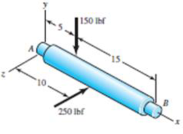
Problem 4-47
Dimensions in inches
Expert Solution & Answer
Want to see the full answer?
Check out a sample textbook solution
Students have asked these similar questions
Answer the value of the deflection at point C. Enter your answer in mm to three decimal places. Assume the positive direction of deflection in the positive direction of v axis.
A gear reduction unit uses the countershaft shown in the figure. Gear A receives power from another gear with the transmitted force
FA applied at the 20° pressure angle as shown. The power is transmitted through the shaft and delivered through gear B through a
transmitted force Fg at the pressure angle shown. For the steel countershaft specified in the table, find the deflection and slope of the
shaft at point A. Use superposition with the deflection equations in Table A-9. Assume the bearings constitute simple supports. In the
figure below, FA is 11400 N and the diameter of the shaft (dshaft) is 52 mm.
20⁰
400 mm
Gear A, 600-mm dia.
350 mm
300 mm
Gear B, 300-mm dia.
The deflection at point A is
The slope at point A is 0.0041 rad.
2.2 mm.
25°
✓
dshaft
es
A gear reduction unit uses the countershaft shown in the figure. Gear A receives power from another gear with the transmitted force
FA applied at the 20° pressure angle as shown. The power is transmitted through the shaft and delivered through gear B through a
transmitted force Fg at the pressure angle shown. For the steel countershaft specified in the table, find the deflection and slope of the
shaft at point A. Use superposition with the deflection equations in Table A-9. Assume the bearings constitute simple supports. In the
figure below, FA is 310 lbf and the diameter of the shaft (dshaft) is 1.29 in.
dshaft
Gear A
20-in dia.
16 in
FA 20⁰
The deflection at point A is
The slope at point A is
14 in
100
Gear B
8-in dia.
rad.
9 in
in.
B
FB
20°
Chapter 4 Solutions
Shigley's Mechanical Engineering Design (McGraw-Hill Series in Mechanical Engineering)
Ch. 4 - The figure shows a torsion bar OA fixed at O,...Ch. 4 - For Prob. 41, if the simple support at point A...Ch. 4 - A torsion-bar spring consists of a prismatic bar,...Ch. 4 - An engineer is forced by geometric considerations...Ch. 4 - A bar in tension has a circular cross section and...Ch. 4 - Prob. 6PCh. 4 - Prob. 7PCh. 4 - Derive the equations given for beam 2 in Table A9...Ch. 4 - Derive the equations given for beam 5 in Table A9...Ch. 4 - The figure shows a cantilever consisting of steel...
Ch. 4 - A simply supported beam loaded by two forces is...Ch. 4 - Using superposition, find the deflection of the...Ch. 4 - A rectangular steel bar supports the two...Ch. 4 - An aluminum tube with outside diameter of 2 in and...Ch. 4 - The cantilever shown in the figure consists of two...Ch. 4 - Using superposition for the bar shown, determine...Ch. 4 - A simply supported beam has a concentrated moment...Ch. 4 - Prob. 18PCh. 4 - Using the results of Prob. 418, use superposition...Ch. 4 - Prob. 20PCh. 4 - Consider the uniformly loaded simply supported...Ch. 4 - Prob. 22PCh. 4 - Prob. 23PCh. 4 - Prob. 24PCh. 4 - Prob. 25PCh. 4 - Prob. 26PCh. 4 - Prob. 27PCh. 4 - Prob. 28PCh. 4 - 429 to 434 For the steel countershaft specified in...Ch. 4 - Prob. 30PCh. 4 - Prob. 31PCh. 4 - Prob. 32PCh. 4 - For the steel countershaft specified in the table,...Ch. 4 - For the steel countershaft specified in the table,...Ch. 4 - Prob. 35PCh. 4 - Prob. 36PCh. 4 - Prob. 37PCh. 4 - Prob. 38PCh. 4 - Prob. 39PCh. 4 - Prob. 40PCh. 4 - The cantilevered handle in the figure is made from...Ch. 4 - Prob. 42PCh. 4 - The cantilevered handle in Prob. 384, p. 154, is...Ch. 4 - A flat-bed trailer is to be designed with a...Ch. 4 - The designer of a shaft usually has a slope...Ch. 4 - Prob. 46PCh. 4 - If the diameter of the steel beam shown is 1.25...Ch. 4 - For the beam of Prob. 4-47, plot the magnitude of...Ch. 4 - Prob. 49PCh. 4 - 4-50 and 4-51 The figure shows a rectangular...Ch. 4 - and 451 the ground at one end and supported by a...Ch. 4 - The figure illustrates a stepped torsion-bar...Ch. 4 - Consider the simply supported beam 5 with a center...Ch. 4 - Prob. 54PCh. 4 - Prob. 55PCh. 4 - Solve Prob. 410 using singularity functions. Use...Ch. 4 - Prob. 57PCh. 4 - Prob. 58PCh. 4 - Prob. 59PCh. 4 - Solve Prob. 413 using singularity functions. Since...Ch. 4 - Prob. 61PCh. 4 - Solve Prob. 419 using singularity functions to...Ch. 4 - Using singularity functions, write the deflection...Ch. 4 - Determine the deflection equation for the...Ch. 4 - Use Castiglianos theorem to verify the maximum...Ch. 4 - Use Castiglianos theorem to verify the maximum...Ch. 4 - Solve Prob. 415 using Castiglianos theorem.Ch. 4 - Solve Prob. 452 using Castiglianos theoremCh. 4 - Determine the deflection at midspan for the beam...Ch. 4 - Using Castiglianos theorem, determine the...Ch. 4 - Solve Prob. 441 using Castiglianos theorem. Since...Ch. 4 - Solve Prob. 442 using Castiglianos theorem.Ch. 4 - The cantilevered handle in Prob. 384 is made from...Ch. 4 - Solve Prob. 450 using Castiglianos theorem.Ch. 4 - Solve Prob. 451 using Castiglianos theorem.Ch. 4 - The steel curved bar shown has a rectangular cross...Ch. 4 - Repeat Prob. 476 to find the vertical deflection...Ch. 4 - For the curved steel beam shown. F = 6.7 kips....Ch. 4 - A steel piston ring has a mean diameter of 70 mm....Ch. 4 - For the steel wire form shown, use Castiglianos...Ch. 4 - 4-81 and 4-82 The part shown is formed from a...Ch. 4 - 4-81 and 4-82 The part shown is formed from a...Ch. 4 - Repeat Prob. 481 for the vertical deflection at...Ch. 4 - Repeat Prob. 482 for the vertical deflection at...Ch. 4 - A hook is formed from a 2-mm-diameter steel wire...Ch. 4 - The figure shows a rectangular member OB, made...Ch. 4 - Prob. 87PCh. 4 - For the wire form shown, determine the deflection...Ch. 4 - Prob. 89PCh. 4 - Prob. 90PCh. 4 - Prob. 91PCh. 4 - Prob. 92PCh. 4 - Solve Prob. 492 using Castiglianos method and...Ch. 4 - An aluminum step bar is loaded as shown. (a)...Ch. 4 - The steel shaft shown in the figure is subjected...Ch. 4 - Repeat Prob. 495 with the diameters of section OA...Ch. 4 - The figure shows a 12- by 1-in rectangular steel...Ch. 4 - For the beam shown, determine the support...Ch. 4 - Solve Prob. 498 using Castiglianos theorem and...Ch. 4 - Consider beam 13 in Table A9, but with flexible...Ch. 4 - Prob. 101PCh. 4 - The steel beam ABCD shown is simply supported at C...Ch. 4 - Prob. 103PCh. 4 - A round tubular column has outside and inside...Ch. 4 - For the conditions of Prob. 4104, show that...Ch. 4 - Link 2, shown in the figure, is 25 mm wide, has...Ch. 4 - Link 3, shown schematically in the figure, acts as...Ch. 4 - The hydraulic cylinder shown in the figure has a...Ch. 4 - The figure shows a schematic drawing of a...Ch. 4 - If drawn, a figure for this problem would resemble...Ch. 4 - Design link CD of the hand-operated toggle press...Ch. 4 - Find the maximum values of the spring force and...Ch. 4 - As shown in the figure, the weight W1 strikes W2...Ch. 4 - Part a of the figure shows a weight W mounted...
Knowledge Booster


Learn more about
Need a deep-dive on the concept behind this application? Look no further. Learn more about this topic, mechanical-engineering and related others by exploring similar questions and additional content below.Similar questions
- -3 The deflection curve for a simple beam AB (see figure) is given by v=q0x360LEI(7L410L2x2+3x4) Describe the load acting on the beam.arrow_forwardFor the wire form shown, use Castigliano's method to determine the deflec- tion of point A in the y direction. Consider the effects of bending and torsion only. Use the straight beam formulation for the bending energy. The wire is steel with E 200 GPa, v = 0.29, and has a diameter of 5 mm. Before cation of the 200-N force the wire form is in the xz plane 100 mm. = appli- where the radius R isarrow_forward4. For the beam shown in the figure determine the following: (El = constant) a. value of El0 at A b. value of El0 at C c. value of Eld at B d. value of Elő at D 300 N/m 1800 N-m A D B C -2 m- - 2 m- -2 m- 2 marrow_forward
- Where is the centroid of the cross-section with respect to the bottom in mm? In reference to Item 1, calculate for the moment of inertia with respect to the neutral axis in mm4. In reference to Item 1, determine the maximum tension bending stresses produced in segment BC of the beam in MPa. In reference to Item 1, determine the maximum compression bending stresses produced in segment BC of the beam in MPa.arrow_forwardThe built-up beam is subjected to a moment of M = 80 kNm. Variable d₁ d₂ d3 da Values for the figure are given in the following table. Note the figure may not be to scale. d5 d3 de d₁ Value 128 mm 22 mm 276 mm 11 mm 138 mm d4 12 mm M₁ de d5 a. Determine the distance from the Neutral Axis to the top of the beam, N.A. b. Determine the mass moment of inertia of the beam, I. Determine the max compressive stress acting on the beam, compression c. d. Determine the max tensile stress acting on the beam, tension.arrow_forwardConsider the T-beam shown in (Figure 1). Take w₁ = 28 kN/m and ₂ = 42 kN/m Figure W1 -3 m- W2 B +1.5m 200 mm 200 mm 20 mm 1 < 1 of 1arrow_forward
- 1. The figure shows Beam Diagram 3 provided by CISC Handbook of Steel Construction, where W=total applied load in kN. (1) using 4th-order differential equation to obtain the deflection equation y (i.e., Ar) for interval 0arrow_forwardMA MB= Mc= MD= Required information For the beam shown, find the reactions at the supports and plot the shear-force and bending-moment diagrams. V=50 lbf/in and V2 = 7 in. NOTE: This is a multi-part question. Once an answer is submitted, you will be unable to return to this part. Hinge = 1400 lbf/ A BI AC R₂ R₁ 4 in 4 in 2 in V1 Determine the values of the moments at points A, B, C, and D. lbf.in lbf.in lbf.in Ibf.in V2 D R₂arrow_forwardThe simply supported W8X24 A-36 steel beam AB is loaded as shown in the figure. What is the slope of point B in radians if w = 5.7 kip/ft, L 16.5 ft, Mo = 6.2 kip-ft? Note: Your answer should include units and be to 4 decimal places. Mo Aरू 늘 -arrow_forwardThe bending moment Mx affects the cross section of the beam given in Figure 4. Beam cross section Calculation of normal stress at points 1,2,3 and normal Plot the stress distribution. a (mm)=255 b (mm)=40 c (mm)=230 d (mm)=50 Mx (kNm)= 53arrow_forwardA T beam supports the three concentrated loads shown in the figure. If load P=1470 lb is applied on specific points along the span. For dimensions of beam 1 in 3P in 4 ft R1 6 ft 6 ft 4 ft R2 Figure P-556 k4 in- 11. The location of the neutral axis from the bottom of the cross-section a. 4 inches b. 3.5 inches c. 2.25 inches d. none of these 12. The value of the moment of inertia (in4) with respect to the neutral axis а. 37 b. 47 c. 67 d. 97 13. The value of the compressive flexure stress а. 10 ksi b. 40 ksi c. 0.1 ksi d. none of these 14. The value of the flexure stress in tension a.40 ksi b. 4 ksi c. 10 ksi d. none of these 15. The value of the horizontal shear stress when load is doubled. а. 40 ksi b. 20 ksi c. both and b d. none of thesearrow_forwardHomework -3- Q1: A simply supported beam as shown in figure (1-A) below, having an I-cross section, has an over all width 200 mm and all depth 300 mm with flanges and web of thickness 20 mm shown in figure (1-B). (a) Draw the shear force and bending moment diagrams of the beam; (b) Determine the maximum compression and tension bending stress which can setup in the beam. 25 20 kN 20 kN 10 kN 150 60 kN/m (All dimensions in mm) 30 kN/m 100 1.5 m Im Im Im 50 50 50 50 50 Figure (1-A) Figure (1-B) Q2: A simply supported beam AB has a length of 3 m and carries distributed load which varies in linear manner from (1w) N/m at A support to (2w) N/m at the B support and concentrated load (1.5w) N at 2 m from A support, and the beam has hollow circular cross section of diameter ratio dindout =1/3. Draw S.F. and B.M. diagrams for the beam and determine the value of (w) if the maximum bending stress 110 N/mm?, and the average shear stress at 1 m from point A equal to 15 N/mm?.arrow_forwardarrow_back_iosSEE MORE QUESTIONSarrow_forward_ios
Recommended textbooks for you
 Mechanics of Materials (MindTap Course List)Mechanical EngineeringISBN:9781337093347Author:Barry J. Goodno, James M. GerePublisher:Cengage Learning
Mechanics of Materials (MindTap Course List)
Mechanical Engineering
ISBN:9781337093347
Author:Barry J. Goodno, James M. Gere
Publisher:Cengage Learning
Solids: Lesson 53 - Slope and Deflection of Beams Intro; Author: Jeff Hanson;https://www.youtube.com/watch?v=I7lTq68JRmY;License: Standard YouTube License, CC-BY