
Shigley's Mechanical Engineering Design (McGraw-Hill Series in Mechanical Engineering)
10th Edition
ISBN: 9780073398204
Author: Richard G Budynas, Keith J Nisbett
Publisher: McGraw-Hill Education
expand_more
expand_more
format_list_bulleted
Concept explainers
Videos
Textbook Question
Chapter 4, Problem 78P
For the curved steel beam shown. F = 6.7 kips. Determine the relative deflection of the applied forces.
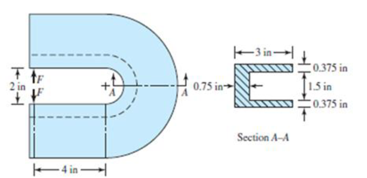
Problem 4-78
Expert Solution & Answer
Want to see the full answer?
Check out a sample textbook solution
Students have asked these similar questions
A gear reduction unit uses the countershaft shown in the figure. Gear A receives power from another gear with the transmitted force
FA applied at the 20° pressure angle as shown. The power is transmitted through the shaft and delivered through gear B through a
transmitted force Fg at the pressure angle shown. For the steel countershaft specified in the table, find the deflection and slope of the
shaft at point A. Use superposition with the deflection equations in Table A-9. Assume the bearings constitute simple supports. In the
figure below, FA is 11400 N and the diameter of the shaft (dshaft) is 52 mm.
20⁰
400 mm
Gear A, 600-mm dia.
350 mm
300 mm
Gear B, 300-mm dia.
The deflection at point A is
The slope at point A is 0.0041 rad.
2.2 mm.
25°
✓
dshaft
3. Determine the displacement and slope (i.e. 0) at the load point for the stepped beam
shown in the following figure. Also determine the reaction forces and moments. Each
element has E = 200 GPa. The area moment of inertia are given as I₁ = 1.25 × 10⁵
mm4, and 2 = 4 x 104 mm. Clearly show the elemental stiffness matrices (k) for
each element, assembly of k matrices to get global stiffness matrix (K) and application of
boundary conditions. Then solve the reduced K matrix to get displacements and reactions
3000 N
150 mm
75 mm
125 mm
For the wire form shown, use Castigliano's method to determine the deflec-
tion of point A in the y direction. Consider the effects of bending and torsion
only. Use the straight beam formulation for the bending energy. The wire is
steel with E 200 GPa, v = 0.29, and has a diameter of 5 mm. Before
cation of the 200-N force the wire form is in the xz plane
100 mm.
=
appli-
where the radius R is
Chapter 4 Solutions
Shigley's Mechanical Engineering Design (McGraw-Hill Series in Mechanical Engineering)
Ch. 4 - The figure shows a torsion bar OA fixed at O,...Ch. 4 - For Prob. 41, if the simple support at point A...Ch. 4 - A torsion-bar spring consists of a prismatic bar,...Ch. 4 - An engineer is forced by geometric considerations...Ch. 4 - A bar in tension has a circular cross section and...Ch. 4 - Prob. 6PCh. 4 - Prob. 7PCh. 4 - Derive the equations given for beam 2 in Table A9...Ch. 4 - Derive the equations given for beam 5 in Table A9...Ch. 4 - The figure shows a cantilever consisting of steel...
Ch. 4 - A simply supported beam loaded by two forces is...Ch. 4 - Using superposition, find the deflection of the...Ch. 4 - A rectangular steel bar supports the two...Ch. 4 - An aluminum tube with outside diameter of 2 in and...Ch. 4 - The cantilever shown in the figure consists of two...Ch. 4 - Using superposition for the bar shown, determine...Ch. 4 - A simply supported beam has a concentrated moment...Ch. 4 - Prob. 18PCh. 4 - Using the results of Prob. 418, use superposition...Ch. 4 - Prob. 20PCh. 4 - Consider the uniformly loaded simply supported...Ch. 4 - Prob. 22PCh. 4 - Prob. 23PCh. 4 - Prob. 24PCh. 4 - Prob. 25PCh. 4 - Prob. 26PCh. 4 - Prob. 27PCh. 4 - Prob. 28PCh. 4 - 429 to 434 For the steel countershaft specified in...Ch. 4 - Prob. 30PCh. 4 - Prob. 31PCh. 4 - Prob. 32PCh. 4 - For the steel countershaft specified in the table,...Ch. 4 - For the steel countershaft specified in the table,...Ch. 4 - Prob. 35PCh. 4 - Prob. 36PCh. 4 - Prob. 37PCh. 4 - Prob. 38PCh. 4 - Prob. 39PCh. 4 - Prob. 40PCh. 4 - The cantilevered handle in the figure is made from...Ch. 4 - Prob. 42PCh. 4 - The cantilevered handle in Prob. 384, p. 154, is...Ch. 4 - A flat-bed trailer is to be designed with a...Ch. 4 - The designer of a shaft usually has a slope...Ch. 4 - Prob. 46PCh. 4 - If the diameter of the steel beam shown is 1.25...Ch. 4 - For the beam of Prob. 4-47, plot the magnitude of...Ch. 4 - Prob. 49PCh. 4 - 4-50 and 4-51 The figure shows a rectangular...Ch. 4 - and 451 the ground at one end and supported by a...Ch. 4 - The figure illustrates a stepped torsion-bar...Ch. 4 - Consider the simply supported beam 5 with a center...Ch. 4 - Prob. 54PCh. 4 - Prob. 55PCh. 4 - Solve Prob. 410 using singularity functions. Use...Ch. 4 - Prob. 57PCh. 4 - Prob. 58PCh. 4 - Prob. 59PCh. 4 - Solve Prob. 413 using singularity functions. Since...Ch. 4 - Prob. 61PCh. 4 - Solve Prob. 419 using singularity functions to...Ch. 4 - Using singularity functions, write the deflection...Ch. 4 - Determine the deflection equation for the...Ch. 4 - Use Castiglianos theorem to verify the maximum...Ch. 4 - Use Castiglianos theorem to verify the maximum...Ch. 4 - Solve Prob. 415 using Castiglianos theorem.Ch. 4 - Solve Prob. 452 using Castiglianos theoremCh. 4 - Determine the deflection at midspan for the beam...Ch. 4 - Using Castiglianos theorem, determine the...Ch. 4 - Solve Prob. 441 using Castiglianos theorem. Since...Ch. 4 - Solve Prob. 442 using Castiglianos theorem.Ch. 4 - The cantilevered handle in Prob. 384 is made from...Ch. 4 - Solve Prob. 450 using Castiglianos theorem.Ch. 4 - Solve Prob. 451 using Castiglianos theorem.Ch. 4 - The steel curved bar shown has a rectangular cross...Ch. 4 - Repeat Prob. 476 to find the vertical deflection...Ch. 4 - For the curved steel beam shown. F = 6.7 kips....Ch. 4 - A steel piston ring has a mean diameter of 70 mm....Ch. 4 - For the steel wire form shown, use Castiglianos...Ch. 4 - 4-81 and 4-82 The part shown is formed from a...Ch. 4 - 4-81 and 4-82 The part shown is formed from a...Ch. 4 - Repeat Prob. 481 for the vertical deflection at...Ch. 4 - Repeat Prob. 482 for the vertical deflection at...Ch. 4 - A hook is formed from a 2-mm-diameter steel wire...Ch. 4 - The figure shows a rectangular member OB, made...Ch. 4 - Prob. 87PCh. 4 - For the wire form shown, determine the deflection...Ch. 4 - Prob. 89PCh. 4 - Prob. 90PCh. 4 - Prob. 91PCh. 4 - Prob. 92PCh. 4 - Solve Prob. 492 using Castiglianos method and...Ch. 4 - An aluminum step bar is loaded as shown. (a)...Ch. 4 - The steel shaft shown in the figure is subjected...Ch. 4 - Repeat Prob. 495 with the diameters of section OA...Ch. 4 - The figure shows a 12- by 1-in rectangular steel...Ch. 4 - For the beam shown, determine the support...Ch. 4 - Solve Prob. 498 using Castiglianos theorem and...Ch. 4 - Consider beam 13 in Table A9, but with flexible...Ch. 4 - Prob. 101PCh. 4 - The steel beam ABCD shown is simply supported at C...Ch. 4 - Prob. 103PCh. 4 - A round tubular column has outside and inside...Ch. 4 - For the conditions of Prob. 4104, show that...Ch. 4 - Link 2, shown in the figure, is 25 mm wide, has...Ch. 4 - Link 3, shown schematically in the figure, acts as...Ch. 4 - The hydraulic cylinder shown in the figure has a...Ch. 4 - The figure shows a schematic drawing of a...Ch. 4 - If drawn, a figure for this problem would resemble...Ch. 4 - Design link CD of the hand-operated toggle press...Ch. 4 - Find the maximum values of the spring force and...Ch. 4 - As shown in the figure, the weight W1 strikes W2...Ch. 4 - Part a of the figure shows a weight W mounted...
Knowledge Booster


Learn more about
Need a deep-dive on the concept behind this application? Look no further. Learn more about this topic, mechanical-engineering and related others by exploring similar questions and additional content below.Similar questions
- The cantilever beam ACE shown in the figure has FlexuraI rigidity EI = 2,1 x 10⁶kip-in". Calculate the downward deflections Scand 8Sat points C and B, respectively, due to the simultaneous action of the moment of 35 kip-in. applied at point C and the concentrated load of 2,5 kips applied at the free end B.arrow_forward-3 The deflection curve for a simple beam AB (see figure) is given by v=q0x360LEI(7L410L2x2+3x4) Describe the load acting on the beam.arrow_forwardA horizontal load P acts at end C of the bracket ABC shown in the figure. Determine the deflection 6Cof point C. Determine the maximum upward deflection 8 of member AB. Note: Assume that the flexural rigidity EI is constant throughout the frame. Also, disregard the effects of axial deformations and consider only the effects of bending due to the load P.arrow_forward
- -33 Find the horizontal deflection hand verti cal deflection vat the free end C of the frame ABC shown in the figure. (The flexural rigidity EI is con stant throughout the frame.) Note: Disregard the effects of axial deformations and consider only the effects of bending due to the load P.arrow_forwardA framework A BCD is acted on by counterclockwise moment M at A (see figure). Assume that Elis constant. Find expressions for reactions at supports B and C Find expressions for angles of rotation at A, 5, C, and Z). Find expressions for horizontal deflections SÂand SD, If length LA3= L12, find length LCDin terms of L for the absolute value of the ratio |sysj=i.arrow_forwardA simple beam with an overhang is subjected to d point load P = 6kN. If the maximum allowable deflect ion at point C is 0.5 mm, select the lightest W360 section from Table F-l{b) that can be used for the beam. Assume that L = 3 m and ignore the distributed weight of the beam.arrow_forward
- -6 Calculate the maximum deflection of a uniformly loaded simple beam if the span length L = 2.0 m, the intensity of the uniform load q = 2.0 kN/m, and the maximum bending stress = 60 MPa, The cross section of the beam is square, and the material is aluminum having modulus of elasticity E = 70 GPa. (Use the formulas of Example 9-1.)arrow_forward-9 Derive the equations of the deflection curve for beam ABC with sliding support at A and roller support at B, supporting a uniform load of intensity q acting on the overhang portion of the beam (see figure). Also, determine deflection cand angle of rotation c. Use the fourth-order differential equation of the deflection curve (the load equation).arrow_forwardThe cantilever beam AB shown in the figure has an extension BCD attached to its free end. A force P acts at the end of the extension. Find the ratio aiL so that the vertical deflection of point B will be zero. Find the ratio aiL so that the angle of rotation at point B will be zero.arrow_forward
- -18 The beam shown in the figure has a sliding support at A and a spring support at B, The sliding support permits vertical movement but no rotation. Derive the equation of the deflection curve and determine the deflection Bat end B due to the uniform load of intensity q. Use the second-order differential equation of the deflection curve.arrow_forwardA framework A BCD is acted on by force P at 2L/3 from 8(see figure). Assume that 7f/is constant. Find expressions for reactions at supports B and C. Find expressions for angles of rotation at A, B* C, and D. Find expressions for horizontal deflections èAand ôD. If length LAB= L i 2, find length LCDin terms of L for the absolute value of the ratioarrow_forwardRepeat Problem 9,5-15 for the anti-symmetric loading shown in the figure.arrow_forward
arrow_back_ios
SEE MORE QUESTIONS
arrow_forward_ios
Recommended textbooks for you
 Mechanics of Materials (MindTap Course List)Mechanical EngineeringISBN:9781337093347Author:Barry J. Goodno, James M. GerePublisher:Cengage Learning
Mechanics of Materials (MindTap Course List)
Mechanical Engineering
ISBN:9781337093347
Author:Barry J. Goodno, James M. Gere
Publisher:Cengage Learning
Column buckling; Author: Amber Book;https://www.youtube.com/watch?v=AvvaCi_Nn94;License: Standard Youtube License