
Shigley's Mechanical Engineering Design (McGraw-Hill Series in Mechanical Engineering)
10th Edition
ISBN: 9780073398204
Author: Richard G Budynas, Keith J Nisbett
Publisher: McGraw-Hill Education
expand_more
expand_more
format_list_bulleted
Videos
Textbook Question
Chapter 4, Problem 88P
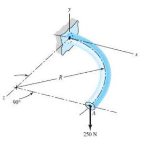
For the wire form shown, determine the deflection of point A in the y direction. Assume R/h.> 10 and consider the effects of bending and torsion only. The wire is steel with E = 200 GPa, v = 0.29, and has a diameter of 6 mm. Before application of the 250-N force the wire form is in the xz plane where the radius R is 80 mm.
Expert Solution & Answer
Want to see the full answer?
Check out a sample textbook solution
Students have asked these similar questions
For the wire form shown, use Castigliano's method to determine the deflec-
tion of point A in the y direction. Consider the effects of bending and torsion
only. Use the straight beam formulation for the bending energy. The wire is
steel with E 200 GPa, v = 0.29, and has a diameter of 5 mm. Before
cation of the 200-N force the wire form is in the xz plane
100 mm.
=
appli-
where the radius R is
Determine the torsion from the following figure. The torsional moment varies in the form of a parabola from 0 to t0 and t (x) = ax + bx + c, GJ is the axial stiffness.
Determine the torsion from the following figure. The torsional moment varies in the form of a parabola from 0 to t0 and t (x) = ax + bx + c, GJ is the axial stiffness. i need help please
Chapter 4 Solutions
Shigley's Mechanical Engineering Design (McGraw-Hill Series in Mechanical Engineering)
Ch. 4 - The figure shows a torsion bar OA fixed at O,...Ch. 4 - For Prob. 41, if the simple support at point A...Ch. 4 - A torsion-bar spring consists of a prismatic bar,...Ch. 4 - An engineer is forced by geometric considerations...Ch. 4 - A bar in tension has a circular cross section and...Ch. 4 - Prob. 6PCh. 4 - Prob. 7PCh. 4 - Derive the equations given for beam 2 in Table A9...Ch. 4 - Derive the equations given for beam 5 in Table A9...Ch. 4 - The figure shows a cantilever consisting of steel...
Ch. 4 - A simply supported beam loaded by two forces is...Ch. 4 - Using superposition, find the deflection of the...Ch. 4 - A rectangular steel bar supports the two...Ch. 4 - An aluminum tube with outside diameter of 2 in and...Ch. 4 - The cantilever shown in the figure consists of two...Ch. 4 - Using superposition for the bar shown, determine...Ch. 4 - A simply supported beam has a concentrated moment...Ch. 4 - Prob. 18PCh. 4 - Using the results of Prob. 418, use superposition...Ch. 4 - Prob. 20PCh. 4 - Consider the uniformly loaded simply supported...Ch. 4 - Prob. 22PCh. 4 - Prob. 23PCh. 4 - Prob. 24PCh. 4 - Prob. 25PCh. 4 - Prob. 26PCh. 4 - Prob. 27PCh. 4 - Prob. 28PCh. 4 - 429 to 434 For the steel countershaft specified in...Ch. 4 - Prob. 30PCh. 4 - Prob. 31PCh. 4 - Prob. 32PCh. 4 - For the steel countershaft specified in the table,...Ch. 4 - For the steel countershaft specified in the table,...Ch. 4 - Prob. 35PCh. 4 - Prob. 36PCh. 4 - Prob. 37PCh. 4 - Prob. 38PCh. 4 - Prob. 39PCh. 4 - Prob. 40PCh. 4 - The cantilevered handle in the figure is made from...Ch. 4 - Prob. 42PCh. 4 - The cantilevered handle in Prob. 384, p. 154, is...Ch. 4 - A flat-bed trailer is to be designed with a...Ch. 4 - The designer of a shaft usually has a slope...Ch. 4 - Prob. 46PCh. 4 - If the diameter of the steel beam shown is 1.25...Ch. 4 - For the beam of Prob. 4-47, plot the magnitude of...Ch. 4 - Prob. 49PCh. 4 - 4-50 and 4-51 The figure shows a rectangular...Ch. 4 - and 451 the ground at one end and supported by a...Ch. 4 - The figure illustrates a stepped torsion-bar...Ch. 4 - Consider the simply supported beam 5 with a center...Ch. 4 - Prob. 54PCh. 4 - Prob. 55PCh. 4 - Solve Prob. 410 using singularity functions. Use...Ch. 4 - Prob. 57PCh. 4 - Prob. 58PCh. 4 - Prob. 59PCh. 4 - Solve Prob. 413 using singularity functions. Since...Ch. 4 - Prob. 61PCh. 4 - Solve Prob. 419 using singularity functions to...Ch. 4 - Using singularity functions, write the deflection...Ch. 4 - Determine the deflection equation for the...Ch. 4 - Use Castiglianos theorem to verify the maximum...Ch. 4 - Use Castiglianos theorem to verify the maximum...Ch. 4 - Solve Prob. 415 using Castiglianos theorem.Ch. 4 - Solve Prob. 452 using Castiglianos theoremCh. 4 - Determine the deflection at midspan for the beam...Ch. 4 - Using Castiglianos theorem, determine the...Ch. 4 - Solve Prob. 441 using Castiglianos theorem. Since...Ch. 4 - Solve Prob. 442 using Castiglianos theorem.Ch. 4 - The cantilevered handle in Prob. 384 is made from...Ch. 4 - Solve Prob. 450 using Castiglianos theorem.Ch. 4 - Solve Prob. 451 using Castiglianos theorem.Ch. 4 - The steel curved bar shown has a rectangular cross...Ch. 4 - Repeat Prob. 476 to find the vertical deflection...Ch. 4 - For the curved steel beam shown. F = 6.7 kips....Ch. 4 - A steel piston ring has a mean diameter of 70 mm....Ch. 4 - For the steel wire form shown, use Castiglianos...Ch. 4 - 4-81 and 4-82 The part shown is formed from a...Ch. 4 - 4-81 and 4-82 The part shown is formed from a...Ch. 4 - Repeat Prob. 481 for the vertical deflection at...Ch. 4 - Repeat Prob. 482 for the vertical deflection at...Ch. 4 - A hook is formed from a 2-mm-diameter steel wire...Ch. 4 - The figure shows a rectangular member OB, made...Ch. 4 - Prob. 87PCh. 4 - For the wire form shown, determine the deflection...Ch. 4 - Prob. 89PCh. 4 - Prob. 90PCh. 4 - Prob. 91PCh. 4 - Prob. 92PCh. 4 - Solve Prob. 492 using Castiglianos method and...Ch. 4 - An aluminum step bar is loaded as shown. (a)...Ch. 4 - The steel shaft shown in the figure is subjected...Ch. 4 - Repeat Prob. 495 with the diameters of section OA...Ch. 4 - The figure shows a 12- by 1-in rectangular steel...Ch. 4 - For the beam shown, determine the support...Ch. 4 - Solve Prob. 498 using Castiglianos theorem and...Ch. 4 - Consider beam 13 in Table A9, but with flexible...Ch. 4 - Prob. 101PCh. 4 - The steel beam ABCD shown is simply supported at C...Ch. 4 - Prob. 103PCh. 4 - A round tubular column has outside and inside...Ch. 4 - For the conditions of Prob. 4104, show that...Ch. 4 - Link 2, shown in the figure, is 25 mm wide, has...Ch. 4 - Link 3, shown schematically in the figure, acts as...Ch. 4 - The hydraulic cylinder shown in the figure has a...Ch. 4 - The figure shows a schematic drawing of a...Ch. 4 - If drawn, a figure for this problem would resemble...Ch. 4 - Design link CD of the hand-operated toggle press...Ch. 4 - Find the maximum values of the spring force and...Ch. 4 - As shown in the figure, the weight W1 strikes W2...Ch. 4 - Part a of the figure shows a weight W mounted...
Knowledge Booster


Learn more about
Need a deep-dive on the concept behind this application? Look no further. Learn more about this topic, mechanical-engineering and related others by exploring similar questions and additional content below.Similar questions
- , Solve the preceding problem using the numerical data: /) = 90mm, h = 280 mm, d = 210 mm, q = 14 kN/m, and L = L2 m.arrow_forwardFind the shear force and bending moment at points B and D. Note: B lies just to the right of the 150 lbf force and D is just to the right of the bearing at C. The bearing at A is a thrust bearing, while the bearing at C is a journal bearing. 150 lb A Answer: VB = -100 lbf MB = 750 lbf in VD = 75lbf Mp = -750 lbf in I 15 in. B 15 in. C. D 75 lb 10 in.arrow_forwardAssume portion ABC of the rod is made of steel (E4e= 200 GPa , v=0.3) and portion CD is made of aluminum (E,lumi = 70 GPa , v=0.25). A 1.75 m Area = 800 mm² 120 kN B 1.25 m C Area = 500 mm² 1.5 m 80 kN D 60 kN The deflection of point C is_ The resulting change in diameter of portion AB of the bar is_arrow_forward
- A beam with a uniform load has a sliding support at one end and spring support at the other. The spring has a stiffness k = 48EI / L3. Derive the equation of the deflection curve by starting with the third-order differential equation (the shear-force equation). Also, determine the angle of rotation θB at support B.arrow_forwardQ4. Under the 5-kip load the support at A rotates 0.002 rad clockwise and settles 0.26 in. (Figure 4). Determine the total vertical deflection at D due to all effects. Consider bending deformations of the member only (i.e., neglect axial deformations). El constant. P = 5 kips 10' O= 0.002 rad B 10' 12' 21 8= 0.26" 8' 8' 6'→arrow_forward2-16. The tapered steel bar shown in the figure is cut out from a steel plate 25 mm thick and is welded at the top to a rigid structure. Find the deflection of the end A caused by the force of 40 kN applied at B. Consider the origin of the coordinate axes at the point of intersection of the sloping lines. E = 210 GN/m². Ans: 0.093 mm. 150 mm 1.5 m 40 kN B 1.5 m 50 mm PROB. 2 – 16arrow_forward
- 2. L=3m 16mm dia. E=200GPA W 5 m 5 m I=10x106 mm When the deflection of the rod is 1mm, compute the force P of the rod.arrow_forwardThe steel beam shown in the figure 2 is made by a steel type that has σY=250 MPa and σU=400MPa Determine the maxium torque that can be applied to the beam when it is bent aroung the x axis.arrow_forwardA spring sustains 200 ft-lb of energy with a deflection of 3’’. Assume that the mean coil diameter is 7 times the wire diameter and that the allowable stress is 100ksi. Determine the wire diameter.arrow_forward
- Q4: Determine the maximum deflection and its location of the simply supported beam shown in the Figure. (E = 200 GPa) and (I= 65.0×105 mm²). 2 m 30 kN 15 kN +2m-20arrow_forwardA gear reduction unit uses the countershaft shown in the figure. Gear A receives power from another gear with the transmitted force FA applied at the 20° pressure angle as shown. The power is transmitted through the shaft and delivered through gear B through a transmitted force Fg at the pressure angle shown. For the steel countershaft specified in the table, find the deflection and slope of the shaft at point A. Use superposition with the deflection equations in Table A-9. Assume the bearings constitute simple supports. In the figure below, FA is 11400 N and the diameter of the shaft (dshaft) is 52 mm. 20⁰ 400 mm Gear A, 600-mm dia. 350 mm 300 mm Gear B, 300-mm dia. The deflection at point A is The slope at point A is 0.0041 rad. 2.2 mm. 25° ✓ dshaftarrow_forwardA solid steel post is subjected to pure torsion. Given: -post Diameter = 65 mm -length = 2.75 m -torque = 2.4 kN-m -shear Modulus of Elasticity = 78 GPa Question: What is the Polar Moment of Inertia of the Post?arrow_forward
arrow_back_ios
SEE MORE QUESTIONS
arrow_forward_ios
Recommended textbooks for you
 Mechanics of Materials (MindTap Course List)Mechanical EngineeringISBN:9781337093347Author:Barry J. Goodno, James M. GerePublisher:Cengage Learning
Mechanics of Materials (MindTap Course List)
Mechanical Engineering
ISBN:9781337093347
Author:Barry J. Goodno, James M. Gere
Publisher:Cengage Learning
Mechanical SPRING DESIGN Strategy and Restrictions in Under 15 Minutes!; Author: Less Boring Lectures;https://www.youtube.com/watch?v=dsWQrzfQt3s;License: Standard Youtube License