
Shigley's Mechanical Engineering Design (McGraw-Hill Series in Mechanical Engineering)
10th Edition
ISBN: 9780073398204
Author: Richard G Budynas, Keith J Nisbett
Publisher: McGraw-Hill Education
expand_more
expand_more
format_list_bulleted
Concept explainers
Videos
Textbook Question
Chapter 4, Problem 70P
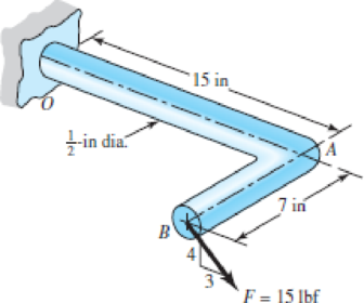
Using Castigliano’s theorem, determine the deflection of point B in the direction of the force F for the steel bar shown.
Problem 4–70
Expert Solution & Answer
Want to see the full answer?
Check out a sample textbook solution
Students have asked these similar questions
The 20-mm diameter steel rod BC is attached to the lever AB and to the fixed support C. The uniform steel lever is 10mm thick and 30mm deep. Using the method of work and energy, determine the deflection of point A when L = 600 mm. Use E = 200 GPa and G = 77.2 GPa
Now solve the problem again but add a torque at point B, which acts together with P as shown in the figure.
In the Figure shown, the rigid beam
with negligible mass was horizontal
before the load P was applied.
Determine the value of load P if the
Steel
A=600 mm2
E=200 GPa
L=2 m
Aluminum
A=900 mm?
E=70 GPa
L=1.5 m
vertical movement at P is 3 mm.
Draw the FBD and deformation
diagram.
1.5 m
1 m
0.5 m
8-30 A three-bar frame is loaded and supported as shown
in Fig.
moment transmitted by
Determine the internal resisting forces and
Section bb in bar ABC.
900 N
250 mm
250 mm
B
D
300 mm
E
300 mm 300 mm
180 mm
180 mm
Chapter 4 Solutions
Shigley's Mechanical Engineering Design (McGraw-Hill Series in Mechanical Engineering)
Ch. 4 - The figure shows a torsion bar OA fixed at O,...Ch. 4 - For Prob. 41, if the simple support at point A...Ch. 4 - A torsion-bar spring consists of a prismatic bar,...Ch. 4 - An engineer is forced by geometric considerations...Ch. 4 - A bar in tension has a circular cross section and...Ch. 4 - Prob. 6PCh. 4 - Prob. 7PCh. 4 - Derive the equations given for beam 2 in Table A9...Ch. 4 - Derive the equations given for beam 5 in Table A9...Ch. 4 - The figure shows a cantilever consisting of steel...
Ch. 4 - A simply supported beam loaded by two forces is...Ch. 4 - Using superposition, find the deflection of the...Ch. 4 - A rectangular steel bar supports the two...Ch. 4 - An aluminum tube with outside diameter of 2 in and...Ch. 4 - The cantilever shown in the figure consists of two...Ch. 4 - Using superposition for the bar shown, determine...Ch. 4 - A simply supported beam has a concentrated moment...Ch. 4 - Prob. 18PCh. 4 - Using the results of Prob. 418, use superposition...Ch. 4 - Prob. 20PCh. 4 - Consider the uniformly loaded simply supported...Ch. 4 - Prob. 22PCh. 4 - Prob. 23PCh. 4 - Prob. 24PCh. 4 - Prob. 25PCh. 4 - Prob. 26PCh. 4 - Prob. 27PCh. 4 - Prob. 28PCh. 4 - 429 to 434 For the steel countershaft specified in...Ch. 4 - Prob. 30PCh. 4 - Prob. 31PCh. 4 - Prob. 32PCh. 4 - For the steel countershaft specified in the table,...Ch. 4 - For the steel countershaft specified in the table,...Ch. 4 - Prob. 35PCh. 4 - Prob. 36PCh. 4 - Prob. 37PCh. 4 - Prob. 38PCh. 4 - Prob. 39PCh. 4 - Prob. 40PCh. 4 - The cantilevered handle in the figure is made from...Ch. 4 - Prob. 42PCh. 4 - The cantilevered handle in Prob. 384, p. 154, is...Ch. 4 - A flat-bed trailer is to be designed with a...Ch. 4 - The designer of a shaft usually has a slope...Ch. 4 - Prob. 46PCh. 4 - If the diameter of the steel beam shown is 1.25...Ch. 4 - For the beam of Prob. 4-47, plot the magnitude of...Ch. 4 - Prob. 49PCh. 4 - 4-50 and 4-51 The figure shows a rectangular...Ch. 4 - and 451 the ground at one end and supported by a...Ch. 4 - The figure illustrates a stepped torsion-bar...Ch. 4 - Consider the simply supported beam 5 with a center...Ch. 4 - Prob. 54PCh. 4 - Prob. 55PCh. 4 - Solve Prob. 410 using singularity functions. Use...Ch. 4 - Prob. 57PCh. 4 - Prob. 58PCh. 4 - Prob. 59PCh. 4 - Solve Prob. 413 using singularity functions. Since...Ch. 4 - Prob. 61PCh. 4 - Solve Prob. 419 using singularity functions to...Ch. 4 - Using singularity functions, write the deflection...Ch. 4 - Determine the deflection equation for the...Ch. 4 - Use Castiglianos theorem to verify the maximum...Ch. 4 - Use Castiglianos theorem to verify the maximum...Ch. 4 - Solve Prob. 415 using Castiglianos theorem.Ch. 4 - Solve Prob. 452 using Castiglianos theoremCh. 4 - Determine the deflection at midspan for the beam...Ch. 4 - Using Castiglianos theorem, determine the...Ch. 4 - Solve Prob. 441 using Castiglianos theorem. Since...Ch. 4 - Solve Prob. 442 using Castiglianos theorem.Ch. 4 - The cantilevered handle in Prob. 384 is made from...Ch. 4 - Solve Prob. 450 using Castiglianos theorem.Ch. 4 - Solve Prob. 451 using Castiglianos theorem.Ch. 4 - The steel curved bar shown has a rectangular cross...Ch. 4 - Repeat Prob. 476 to find the vertical deflection...Ch. 4 - For the curved steel beam shown. F = 6.7 kips....Ch. 4 - A steel piston ring has a mean diameter of 70 mm....Ch. 4 - For the steel wire form shown, use Castiglianos...Ch. 4 - 4-81 and 4-82 The part shown is formed from a...Ch. 4 - 4-81 and 4-82 The part shown is formed from a...Ch. 4 - Repeat Prob. 481 for the vertical deflection at...Ch. 4 - Repeat Prob. 482 for the vertical deflection at...Ch. 4 - A hook is formed from a 2-mm-diameter steel wire...Ch. 4 - The figure shows a rectangular member OB, made...Ch. 4 - Prob. 87PCh. 4 - For the wire form shown, determine the deflection...Ch. 4 - Prob. 89PCh. 4 - Prob. 90PCh. 4 - Prob. 91PCh. 4 - Prob. 92PCh. 4 - Solve Prob. 492 using Castiglianos method and...Ch. 4 - An aluminum step bar is loaded as shown. (a)...Ch. 4 - The steel shaft shown in the figure is subjected...Ch. 4 - Repeat Prob. 495 with the diameters of section OA...Ch. 4 - The figure shows a 12- by 1-in rectangular steel...Ch. 4 - For the beam shown, determine the support...Ch. 4 - Solve Prob. 498 using Castiglianos theorem and...Ch. 4 - Consider beam 13 in Table A9, but with flexible...Ch. 4 - Prob. 101PCh. 4 - The steel beam ABCD shown is simply supported at C...Ch. 4 - Prob. 103PCh. 4 - A round tubular column has outside and inside...Ch. 4 - For the conditions of Prob. 4104, show that...Ch. 4 - Link 2, shown in the figure, is 25 mm wide, has...Ch. 4 - Link 3, shown schematically in the figure, acts as...Ch. 4 - The hydraulic cylinder shown in the figure has a...Ch. 4 - The figure shows a schematic drawing of a...Ch. 4 - If drawn, a figure for this problem would resemble...Ch. 4 - Design link CD of the hand-operated toggle press...Ch. 4 - Find the maximum values of the spring force and...Ch. 4 - As shown in the figure, the weight W1 strikes W2...Ch. 4 - Part a of the figure shows a weight W mounted...
Knowledge Booster


Learn more about
Need a deep-dive on the concept behind this application? Look no further. Learn more about this topic, mechanical-engineering and related others by exploring similar questions and additional content below.Similar questions
- The Z-section of Example D-7 is subjected to M = 5 kN · m, as shown. Determine the orientation of the neutral axis and calculate the maximum tensile stress c1and maximum compressive stress ocin the beam. Use the following numerical data: height; = 200 mm, width ft = 90 mm, constant thickness a = 15 mm, and B = 19.2e. Use = 32.6 × 106 mm4 and I2= 2.4 × 10e mm4 from Example D-7arrow_forwardA frame ABC is loaded at point C by a force P acting at an angle öf to the horizontal (see figure). Both members of the frame have the same length and the same flexural rigidity. Determine the angle a so that the deflection of point C is in the same direction as the load. (Disregard the effects of axial deformations and consider only the effects of bending due to the load P.) Note: A direction of loading such that the resulting deflection is in the same direction as the load is called a principal direction. For a given load on a planar structure, there are two principal directions that are perpendicular to each other.arrow_forward, Solve the preceding problem using the numerical data: /) = 90mm, h = 280 mm, d = 210 mm, q = 14 kN/m, and L = L2 m.arrow_forward
- -7 Repeat Problem 2.3-5, but n include the weight of the bar. See Table I-I in Appendix I for the weight density of steel.arrow_forward‘11.5-2 A steel bar having a square cross section (50 mm × 50 mm)and length L = 2.0 in is compressed by axial loads that have a resultant P = 60 kN acting at the midpoint of one side of the cross section (sec figure). Assuming that the modulus of elasticity £is equal to 210 GPa and that the ends of the bar are pinned, calculate the maximum deflection S and the maximum bending moment Mmax.arrow_forwardA horizontal load P acts at end C of the bracket ABC shown in the figure. Determine the deflection 6Cof point C. Determine the maximum upward deflection 8 of member AB. Note: Assume that the flexural rigidity EI is constant throughout the frame. Also, disregard the effects of axial deformations and consider only the effects of bending due to the load P.arrow_forward
- -33 Find the horizontal deflection hand verti cal deflection vat the free end C of the frame ABC shown in the figure. (The flexural rigidity EI is con stant throughout the frame.) Note: Disregard the effects of axial deformations and consider only the effects of bending due to the load P.arrow_forwardThe cross section of a sign post of constant thickness is shown in the figure. Derive the formula for the distance e from the cent crime of the wall of the post to the shear center S: where I2. = moment of inertia about the z axis. Also, compare this formula with that given in Problem 6.9-11 for the special case of ß = 0 here and a = h/2 in both formulas.arrow_forwardFind the controlling buckling load (kN) for the steel column shown in the figure. The column is pinned at top and bottom and is made up of two C 150 x 12,2 shapes that act together. Assume that E = 205 GPa and L = 6 m.arrow_forward
- An aluminum box column with a square cross section is fixed at the base and free at the top (sec figure). The outside dimension b of each side is 100 mm and the thickness t of the wall is 8 mm. The resultant of the compressive loads acting on the top of the column is a force P = 50 kN acting at the outer edge of the column at the midpoint of one side. What is the longest permissible length Lmaxof the column if the deflection at the top is not to exceed 30 mm? (Assume E = 73 GPaarrow_forwardIn the element in the figure, the bars are made of UNSG 10100 HR steel (Sy= 26 Kpsi and E= 30x106 psi). Determine the maximum weight that the system can support.arrow_forward8-30 A three-bar frame is loaded and supported as shown in Fig. moment transmitted by Determine the internal resisting forces and Section aa in bar BD. 900 N 250 mm 250 mm 300 mm E 300 mm 300) mm 180 mm 180 mmarrow_forward
arrow_back_ios
SEE MORE QUESTIONS
arrow_forward_ios
Recommended textbooks for you
 Mechanics of Materials (MindTap Course List)Mechanical EngineeringISBN:9781337093347Author:Barry J. Goodno, James M. GerePublisher:Cengage Learning
Mechanics of Materials (MindTap Course List)
Mechanical Engineering
ISBN:9781337093347
Author:Barry J. Goodno, James M. Gere
Publisher:Cengage Learning
Column buckling; Author: Amber Book;https://www.youtube.com/watch?v=AvvaCi_Nn94;License: Standard Youtube License